Vehicle body lower structure
A body and structure technology, applied in the field of body substructure, can solve the problems of increasing fuel consumption, difficult to take into account, deterioration, etc., and achieve the effect of high load transmission efficiency
- Summary
- Abstract
- Description
- Claims
- Application Information
AI Technical Summary
Problems solved by technology
Method used
Image

Examples
Embodiment 1
[0182] In order to confirm the effect of the present invention, the weight and rigidity were numerically calculated and compared between the subframe of the above-mentioned embodiment (invention example 1) and the subframe of comparative example 1.
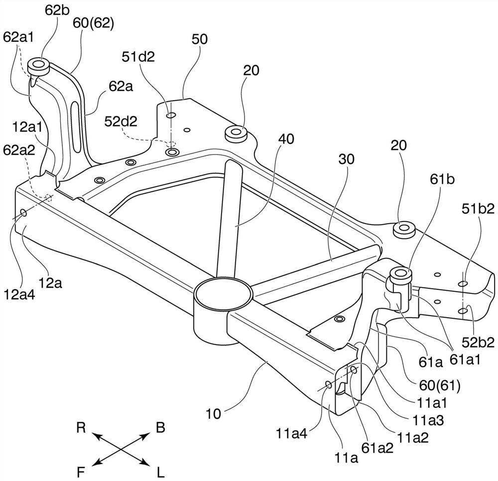
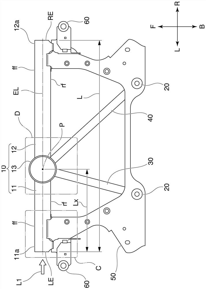
[0183] Invention example 1 has figure 1 construction shown. That is, in Invention Example 1, the extension line b1 including the first axis b passing through the centroid at each position in the longitudinal direction of the connecting member 30 and the first axis b passing through the centroid at each position in the longitudinal direction of the connecting member 40 2 The extension line c1 of the axis c is viewed in a vertical section at the position of the intersection point P and perpendicular to the longitudinal direction of the front cross member 10 in plan view, the extension line b1 of the first axis b and the extension line c1 of the second axis c Located on the inner side of the front cross member 10 . In addition, whe...
Embodiment 2
[0193] Next, in order to confirm Invention Example 2 ( Figure 14A ) of the connecting parts 30, 40 for the effect of the rigidity of the support structure, prepared Figure 14B ~ Figure 14D Comparing the calculation models shown, the height of rigidity when a common external force is applied to each calculation model is compared.
[0194] First, each calculation model is explained, Figure 14A It is a top view of the front sub frame of the second invention example. Invention example 2 has with figure 1 The shown front subframe has the same configuration.
[0195] Figure 14B is instead Figure 14A The connection members 30 and 40 shown are comparative example 2 using the connection members 30A and 40A. These connecting members 30A, 40A have the same outer diameter and inner diameter as the connecting members 30 , 40 , but are joined to the rear side surface of the front cross member 10 while being spaced from each other in the left-right direction. Therefore, in this c...
Embodiment 3
[0205] exist figure 1 In the shown front subframe, the rigidity of the front cross member 10 tends to increase as the plate thickness of the engine mount 13 is increased. On the other hand, if the plate thickness is excessively increased, the weight of the engine mount 13 increases, and as a result, the weight efficiency of rigidity tends to decrease. Therefore, there is a preferable plate thickness ratio from the viewpoint of rigid weight efficiency.
[0206] Thus, in figure 1 In the shown front auxiliary frame, the minimum plate thickness t of the engine bracket 13 F (mm) and the average thickness t of the linear parts 11c and 12c C (mm) The ratio between is set to t C / t F , find out how the weight efficiency of rigidity is displaced by numerical calculation.
[0207] As a condition for numerical calculation, first, the figure 1 The shown front subframe is fixed to the vehicle body at four points at a pair of rear body frames 20 and a pair of front body frames 60 . ...
PUM
 Abstract
Description
Claims
Application Information
 - R&D
- Intellectual Property
- Life Sciences
- Materials
- Tech Scout
- Unparalleled Data Quality
- Higher Quality Content
- 60% Fewer Hallucinations
Browse by: Latest US Patents, China's latest patents, Technical Efficacy Thesaurus, Application Domain, Technology Topic, Popular Technical Reports.
© 2025 PatSnap. All rights reserved.Legal|Privacy policy|Modern Slavery Act Transparency Statement|Sitemap|About US| Contact US: help@patsnap.com