Pneumatic buffering method, pneumatic buffering device and pneumatic transmission equipment

A buffering method and technology of a buffering device are applied in the field of item transport and can solve the problem of difficulty in obtaining the weight of the sample tube and the like

Active Publication Date: 2021-10-22
KINGCON INTELLIGENT TECH CO LTD
View PDF13 Cites 3 Cited by
  • Summary
  • Abstract
  • Description
  • Claims
  • Application Information

AI Technical Summary

Problems solved by technology

This method needs to obtain the weight of the sample tube in advance, but when the type of sample tube is different, the quality of the loaded sample is also different, so it is difficult to obtain the weight of the sample tube conveniently

Method used


Image

  • Pneumatic buffering method, pneumatic buffering device and pneumatic transmission equipment
  • Pneumatic buffering method, pneumatic buffering device and pneumatic transmission equipment
  • Pneumatic buffering method, pneumatic buffering device and pneumatic transmission equipment

Examples


Embodiment Construction

[0046]The following description serves to disclose the present invention to enable those skilled in the art to carry out the present invention. The preferred embodiments described below are only examples, and those skilled in the art can devise other obvious variations. The basic principles of the present invention defined in the following description can be applied to other embodiments, variations, improvements, equivalents and other technical solutions without departing from the spirit and scope of the present invention.

[0047] Those skilled in the art should understand that in the disclosure of the present invention, the terms "vertical", "transverse", "upper", "lower", "front", "rear", "left", "right", " The orientation or positional relationship indicated by "vertical", "horizontal", "top", "bottom", "inner", "outer", etc. is based on the orientation or positional relationship shown in the drawings, which are only for the convenience of describing the present invention ...


PUM


Abstract

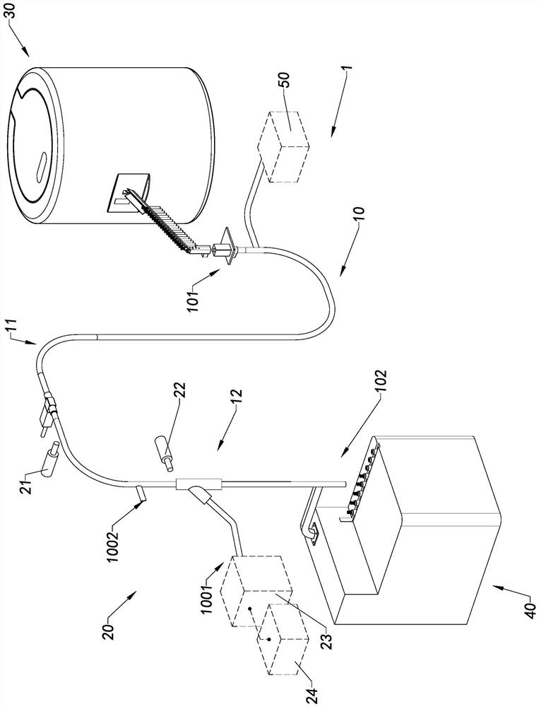
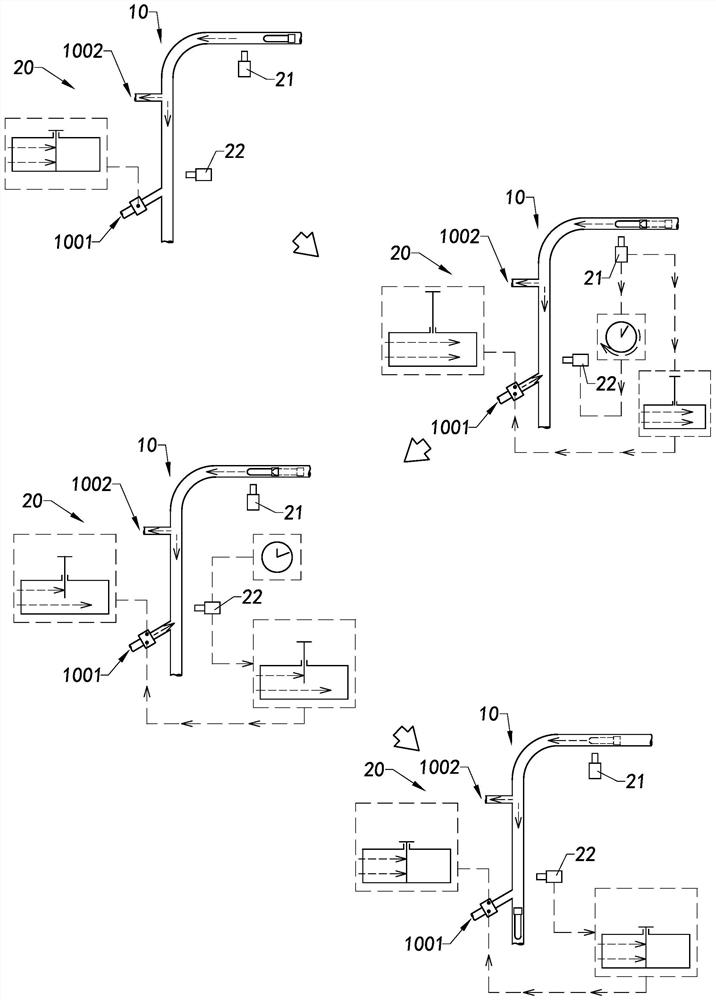
The invention provides a pneumatic buffering method, a pneumatic buffering device and pneumatic conveying equipment. The pneumatic buffering method comprises the following steps that an article conveyed towards a pipeline outlet in a conveying pipeline is buffered through airflow, and the buffering airflow is provided by a buffering power source; and the buffered conveyed article is detected at a preset position in the advancing direction of the conveyed article so as to judge whether the conveyed article passes or not within preset time, and if not, the buffering power source is controlled so as to provide integrally-decreased buffering resistance for the conveyed article within follow-up time.

Description

technical field [0001] The invention relates to the field of article transmission, in particular to a pneumatic buffer method, a pneumatic buffer device and pneumatic transmission equipment. Background technique [0002] During the conveying process of items, for example, during the conveying process of sample tubes, the sample tube loaded with samples moves forward in the conveying pipeline under the push of the airflow, and when the sample tube reaches the outlet of the conveying pipeline, it usually has a certain speed . For heavy sample tubes, if the speed of the sample tube is within the appropriate range, the sample tube will fall smoothly to the designated place, but for light sample tubes, if the same airflow Under push, the light weight sample tube may rush out of the transfer pipe at a relatively high speed, which may cause damage to the sample loaded inside the sample tube. [0003] In order to avoid this situation, a buffer air flow will be set at or near the o...

Claims


Application Information

Patent Timeline
Patent Type & Authority Applications(China)
IPC IPC(8): B65G51/16B65G51/36
CPCB65G51/16B65G51/36
Inventor 杨以杭
Owner KINGCON INTELLIGENT TECH CO LTD
Why Eureka
Try Eureka