
New energy automobile shockproof battery

A new energy vehicle and battery technology, applied in the direction of secondary batteries, battery pack components, circuits, etc., can solve the problems of reducing battery life, dust entry, impact, etc., and achieve the effect of prolonging service life

Inactive Publication Date: 2020-11-03
吴鞠躬
View PDF0 Cites 3 Cited by
  • Summary
  • Abstract
  • Description
  • Claims
  • Application Information

AI Technical Summary

Problems solved by technology

[0003] At present, since the car battery is generally installed under the car chassis, and there is no buffer and shock absorbing device between the battery and the car chassis, when the car is driving on a road with poor road conditions, it is likely that the battery will be damaged due to the low car chassis. Scuffing between the bottom and the ground will cause the deformation of the battery case to affect the life of the internal battery. When the car is bumped, the single battery inside the battery case will be misplaced, resulting in an internal circuit break of the battery, and the existing new energy vehicles When the battery is working, it will generate a lot of heat. The existing battery case has ventilation holes, which will easily cause a lot of dust to enter during driving, and it will easily cause a short circuit of the battery when the vehicle is wading, reducing the service life of the battery.

Method used


Image

  • New energy automobile shockproof battery
  • New energy automobile shockproof battery
  • New energy automobile shockproof battery

Examples


Embodiment Construction

[0025] The following will clearly and completely describe the technical solutions in the embodiments of the present invention with reference to the accompanying drawings in the embodiments of the present invention. Obviously, the described embodiments are only some, not all, embodiments of the present invention. Based on the embodiments of the present invention, all other embodiments obtained by persons of ordinary skill in the art without making creative efforts belong to the protection scope of the present invention.

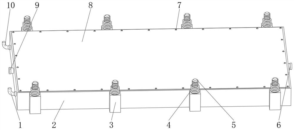
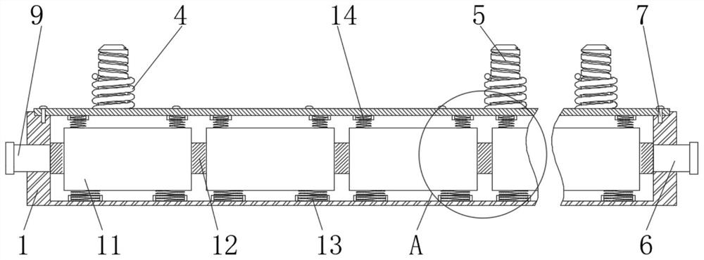
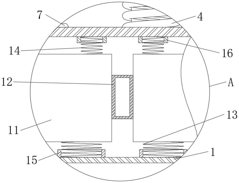
[0026] see Figure 1-4 , a shockproof battery for a new energy vehicle, comprising a battery case 2, the side of the battery case 2 is fixedly connected with a mounting post 3, the height of the mounting post 3 is equal to the thickness of the battery case 2, and there are several mounting posts 3, several The mounting columns 3 are equally divided into two groups, and the mounting columns 3 of each group are evenly spaced. Holes 19, through holes 19 communic...


PUM


Abstract

The invention discloses a new energy automobile shockproof battery, and relates to the technical field of automobile batteries. The new energy automobile shockproof battery comprises a battery outer shell, the side surface of the battery outer shell is fixedly connected with a mounting column, and the inner side wall of the battery outer shell is fixedly connected with a cooling frame. By arranging the mounting column, the top damping spring and the bottom damping spring can be fixed in the mounting column, the top damping spring and the bottom damping spring can deform to achieve the buffering purpose when the bottom of an automobile makes contact with a road, and the lower spring and the upper spring can form up-down limiting on a single battery, and achieve the damping effect; by arranging the cooling frame, the cooling frame can be communicated with a cooling water tank at the front part of the automobile through a water inlet pipe and a water outlet pipe, and when the working temperature of a single battery rises, an external water pump can be used for pumping cooling water in the cooling water tank into the cooling frame, so that the single battery can be cooled, and the purpose of prolonging the service life of a single battery is achieved.

Description

technical field [0001] The invention relates to the technical field of automobile batteries, in particular to a shockproof battery for new energy automobiles. Background technique [0002] New energy vehicles refer to the use of unconventional vehicle fuels as power sources (or the use of conventional vehicle fuels, the use of new vehicle power devices), integrated vehicle power control and advanced technology in driving, the formation of advanced technical principles, with Automobiles with new technology and new structure. With the development of new energy vehicles, there are more and more innovations in new energy vehicle batteries. New energy vehicle batteries can be divided into two categories, namely batteries and fuel cells. Batteries are suitable for pure new energy vehicles and can be classified as lead-acid batteries, nickel-based batteries (nickel-hydrogen and nickel-metal hydride batteries, nickel-fu and nickel-zinc batteries), sodium beta batteries (sodium-sul...

Claims


Application Information

Patent Timeline
Patent Type & Authority Applications(China)
IPC IPC(8): H01M2/10H01M10/613H01M10/625H01M10/655H01M10/6567
CPCH01M10/613H01M10/625H01M10/655H01M10/6567Y02E60/10
Inventor 吴鞠躬郭刘林
Owner 吴鞠躬
Learn More