Energy absorption connecting device

A connecting device and connecting technology, applied in the direction of shock absorber, spring/shock absorber, elastic shock absorber, etc., can solve the problems of reduced safety performance, complex structure, waste and other problems

Active Publication Date: 2014-01-01
苏州云逸航空复合材料结构有限公司
View PDF7 Cites 3 Cited by
  • Summary
  • Abstract
  • Description
  • Claims
  • Application Information

AI Technical Summary

Problems solved by technology

In short, there are various structural forms of energy-absorbing buffers, but the above-mentioned traditional energy-absorbing structures are only simple energy-absorbing buffer devices with single functions.
When a product equipped with an energy-absorbing device is working normally, the energy-absorbing device is an idle, non-load-bearing structure, which also causes a certain amount of waste to some extent
[0003] On the other hand, the structure of the current energy-absorbing buffer device is too complicated, and the probability of failure is relatively high, which means that the safety performance is reduced

Method used


Image

  • Energy absorption connecting device
  • Energy absorption connecting device
  • Energy absorption connecting device

Examples


Embodiment 1

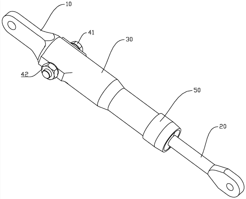
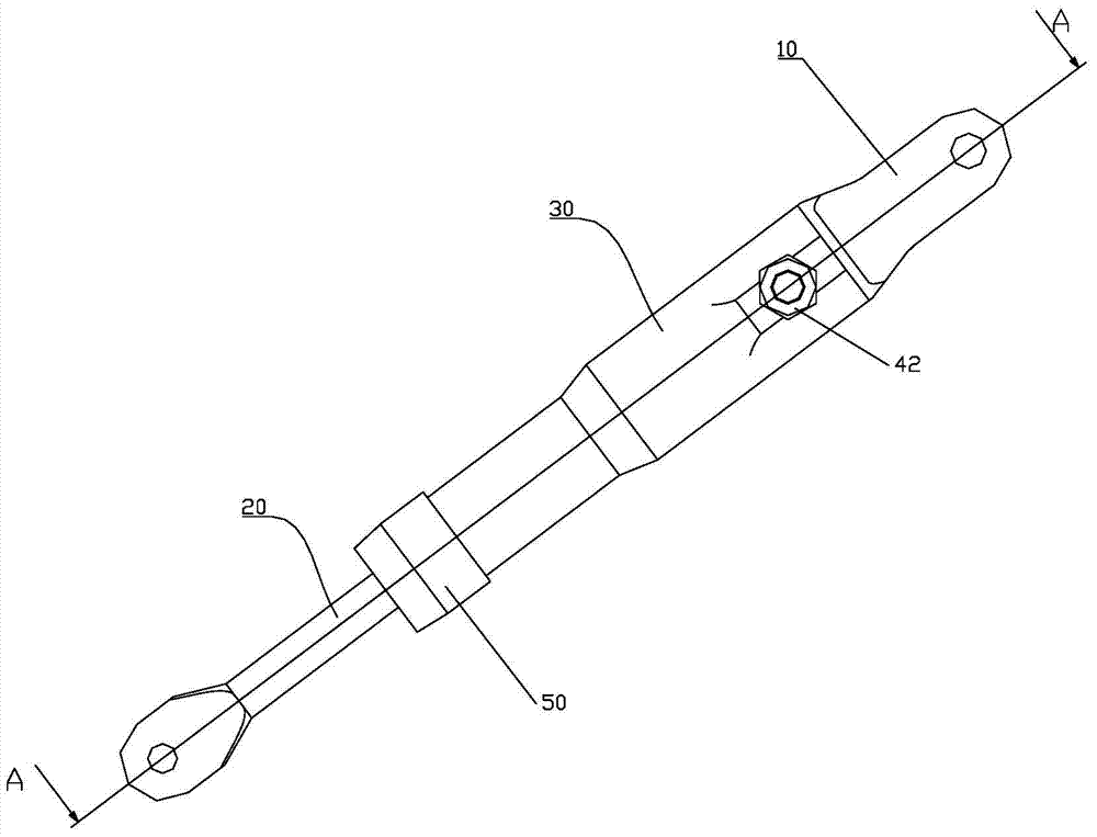
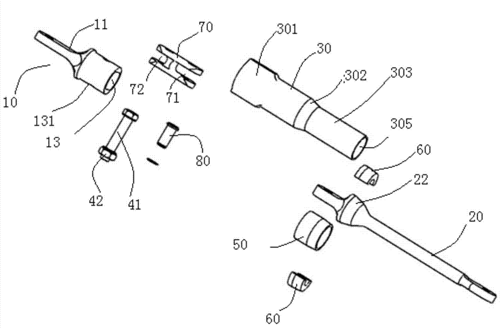
[0047] Such as Figure 1 to Figure 4 As shown, the energy-absorbing connection device is used to connect two connected devices, and includes a first joint 10, a second joint 20, and a connecting sleeve 30. The first joint 10 and the second joint 20 are respectively connected to a connected device. The connection method of the first joint 10 and the connected device can adopt the existing technology. The connection method of the second joint 20 and the connected device can adopt the existing technology. The cross-sectional shape of the first joint 10, the second joint 20, and the connecting sleeve 30 can be set according to the application. The cross section is a section perpendicular to the axis. In this embodiment, the cross section is circular as an example. The first joint 10 includes a flat connecting rod 11 and a cavity 13.

[0048] The connecting sleeve 30 has a tube wall 304 and a circular lumen 305. The connecting sleeve 30 has a accommodating section 301 and an exp...

Embodiment 2

[0056] Such as Figure 5 As shown, the difference in structure from Embodiment 1 is that only the first groove 71 is provided in the adapter 70. One end of the second groove 72 is a solid cylinder. The rest of the structure is the same as the first embodiment.

Embodiment 3

[0058] Such as Image 6 As shown, the energy-absorbing connection device is used to connect two connected devices, and includes a first joint 10, a second joint 20, and a connecting sleeve 30. The first joint 10 and the second joint 20 are respectively connected to a connected device. The connection method of the first joint 10 and the connected device can adopt the existing technology. The connection method of the second joint 20 and the connected device can adopt the existing technology. The cross-sectional shape of the first joint 10, the second joint 20, and the connecting sleeve 30 can be set according to the application. The cross section is a section perpendicular to the axis. In this embodiment, the cross section is circular as an example. The first joint 10 includes a flat connecting rod 11 and a cavity 13.

[0059] The connecting sleeve 30 has a tube wall 304 and a circular lumen 305. The connecting sleeve 30 has a accommodating section 301 and an expansion section...


PUM


Abstract

The invention discloses an energy absorption connecting device. The energy absorption connecting device is characterized by comprising a first connecting head which is used for connecting with one being connected device, a second connecting head which is used for connecting with the other connecting device, a connecting sleeve which is provided with the pipe wall and the pipe chamber and an expansion inner core which is arranged inside the pipe chamber; one end of the connecting sleeve is connected with the first connecting head; the expansion inner core is arranged on the second connecting head; the first connecting head and the second connecting head are connected inside the pipe chamber through the expansion inner core or a connecting part or connected inside the pipe chamber through the expansion inner core and the connecting part. The energy absorption connecting device which absorbs energy can play roles of connection devices and heat absorption devices.

Description

Technical field [0001] The invention relates to an energy-absorbing connection device. Background technique [0002] With the advancement of science and technology and the improvement of living standards, while we are pursuing faster and more comfortable transportation, we also have higher requirements for safety. This requires that the speed of our transportation can not only be increased, but also Come down safely. This has led to an upsurge in the research of energy-absorbing buffer devices, such as common car seat belts, bumpers, airbags, and composite honeycomb structures. At the same time, energy-absorbing buffer devices have also been widely studied and applied in the aerospace field. For example, the landing gear of spacecraft, the hydraulic energy absorbing device of aircraft landing gear, etc. In short, the structure of the energy absorbing buffer is various, but the above traditional energy absorbing structure is just a simple energy absorbing buffer device with sing...

Claims


Application Information

Patent Timeline
Patent Type & Authority Applications(China)
IPC IPC(8): F16F7/00F16F7/12
Inventor 徐磊赖毓康
Owner 苏州云逸航空复合材料结构有限公司
Why Eureka
Try Eureka