Eureka AIR delivers breakthrough ideas for toughest innovation challenges, trusted by R&D personnel around the world.

Jacking equipment of steel structure beam for installation of small factory building

A technology for installation of steel structure beams, applied in the direction of lifting frames, lifting devices, building structures, etc., can solve the problems of steel beam jacking position deviation, inability to lock the walking wheels, and affect the construction process, so as to avoid device displacement and loosening , the effect of ensuring safety

Active Publication Date: 2021-10-22
北京嘉恒广泰建筑工程有限公司
View PDF4 Cites 2 Cited by
  • Summary
  • Abstract
  • Description
  • Claims
  • Application Information

AI Technical Summary

Problems solved by technology

[0004] The object of the present invention is to provide a jacking device for steel structure beams for installation in a small factory building, which has stable operation and high safety in use. After the beam is transported, it is automatically unlocked, so that the device can move freely, which solves the problem that the traditional device cannot lock the walking wheels at the bottom when it is jacked up, and the device may move by itself, resulting in the jacking position of the steel beam. Deviation occurs, which affects the normal construction process of operators

Method used


Image

  • Jacking equipment of steel structure beam for installation of small factory building
  • Jacking equipment of steel structure beam for installation of small factory building
  • Jacking equipment of steel structure beam for installation of small factory building

Examples


Embodiment Construction

[0025] The following will clearly and completely describe the technical solutions in the embodiments of the present invention with reference to the accompanying drawings in the embodiments of the present invention. Obviously, the described embodiments are only some, not all, embodiments of the present invention. Based on the embodiments of the present invention, all other embodiments obtained by persons of ordinary skill in the art without making creative efforts belong to the protection scope of the present invention.

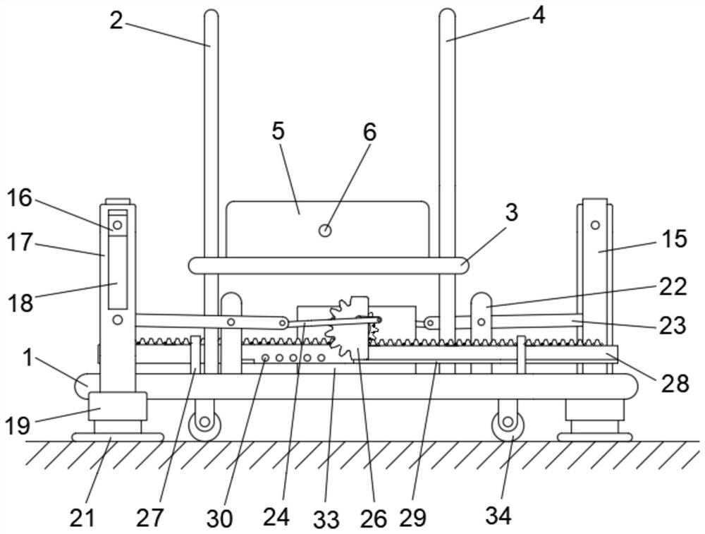
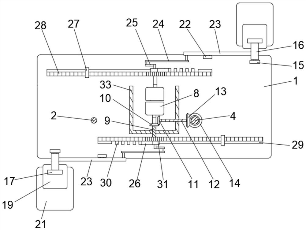
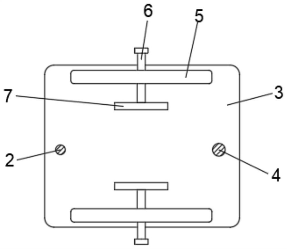
[0026] see Figure 1 to Figure 6 , the present invention provides a technical solution: a jacking device for steel structure beams for installation in a small factory building, including an operating base 1, the surface of the operating base 1 is fixedly connected with a support rod 2, and the surface of the support rod 2 penetrates through the An opening is provided, and the support rod 2 is slidably sleeved with a bearing plate 3 through the opening, and a t...


PUM


Abstract

The invention discloses jacking equipment of a steel structure beam for installation of a small factory building, and relates to the technical field of steel beam jacking devices. The jacking equipment comprises an operation base, a supporting rod is fixedly connected to the surface of the operation base, an opening is formed in the surface of the supporting rod in a penetrating manner, and the supporting rod is slidably connected with a bearing plate in a sleeving manner through the opening; and a first threaded hole is formed in the surface of the bearing plate. Through mutual cooperation of the structures, the equipment has the effects that operation is stable, use safety is high, a fixing base is firmly connected with the ground in the jacking process in an abutting manner, the equipment is prevented from loosening, and the equipment can freely move due to automatic unlocking after steel beam transportation is completed, and the problem that when a traditional device is used for jacking, normal construction process of operators is affected by deviation of the jacking position of a steel beam due to the fact that the device can move due to the fact that walking wheels at the bottom cannot be automatically locked in the prior art is solved.

Description

technical field [0001] The invention relates to the technical field of steel beam jacking devices, in particular to jacking equipment for steel structural beams used for installation in small workshops. Background technique [0002] When installing the steel beam structure of the factory building, it needs to be hoisted and lifted, and the traditional lifting device is inconvenient, such as a jacking device for steel structure beams for small factory building installation disclosed in Chinese patent CN201811545626.5. The device is designed with an adjustment mechanism, which can adjust the distance between the two walking platforms, so that the jacking device on the walking platform can stably support a larger steel structure beam, ensuring the stability of the steel structure beam during the jacking process Through the clamping mechanism, the clamping mechanism can be clamped and fixed when the steel structure beam is lifted to a suitable position, so as to avoid the phenom...

Claims


Application Information

Patent Timeline
Patent Type & Authority Applications(China)
IPC IPC(8): B66F7/28B66F7/00E04G21/16
CPCB66F7/28B66F7/025E04G21/162Y02B50/00
Inventor 缪雨彤缪文浩夏欢欢
Owner 北京嘉恒广泰建筑工程有限公司
Why Eureka
Eureka Blog
Learn More