A ZWY type mine crawler excavator loader multifunctional conveying device

A multi-functional conveying and loader technology, applied in the direction of conveyor, loading/unloading, transportation and packaging, etc., can solve the problems of low efficiency and manpower consumption, and achieve the effect of ensuring safety, stable operation and compact structure

Active Publication Date: 2021-11-26
HEFEI UNIV +1
View PDF7 Cites 2 Cited by
  • Summary
  • Abstract
  • Description
  • Claims
  • Application Information

AI Technical Summary

Problems solved by technology

[0005] The purpose of the present invention is to solve the problem of labor-intensive and low efficiency in the prior art, and propose a ZWY type mining crawler excavator loader multifunctional conveying device

Method used


Image

  • A ZWY type mine crawler excavator loader multifunctional conveying device
  • A ZWY type mine crawler excavator loader multifunctional conveying device
  • A ZWY type mine crawler excavator loader multifunctional conveying device

Examples


Embodiment 1

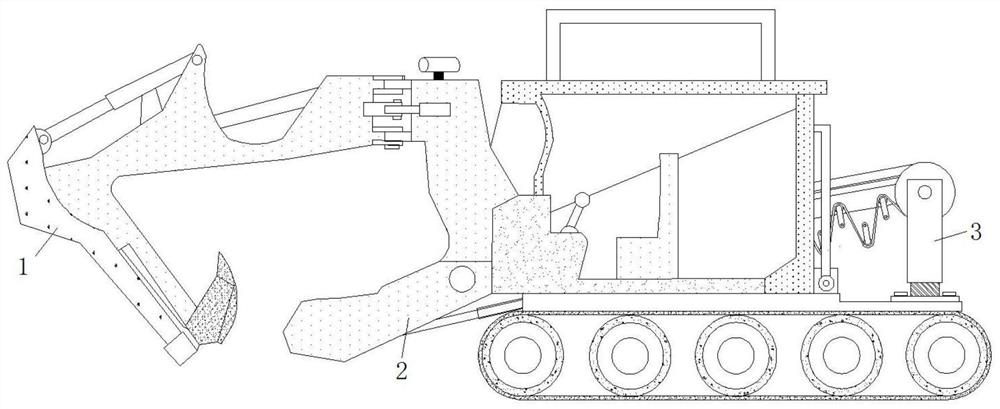
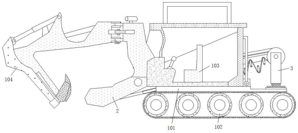
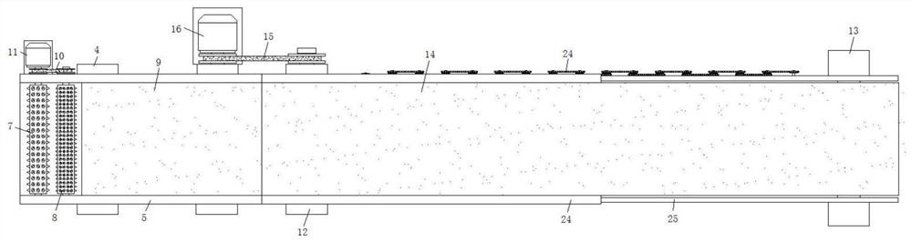
[0030] refer to Figure 1-6 , a ZWY type mining crawler excavator loader multifunctional conveying device, including a loader body 1, the loader body 1 includes a base 101, a drive crawler 102 is installed on the lower end of the base 101, and a driver's cab 103 is fixed on the upper end of the base 101, An excavation mechanism 104 is installed on the front side of the base, and a rolling feeding mechanism 2 and a transmission mechanism 3 are respectively installed on both sides of the rear end of the base 101. The rolling feeding mechanism 2 includes a mounting seat 14, which is fixed by screws A rectangular dish 5 is connected, and the two sides of the rectangular dish 5 are connected through. A rolling block 6 is fixed on the inner bottom of the rectangular dish 5 close to the side of the excavating mechanism 104. The upper end of the rolling block 6 is provided with a rolling roller 7 and a rolling block. Roller two 8, and rolling roller one 7 and rolling roller two 8 are ...

Embodiment 2

[0033] Such as image 3 , 5 As shown in and 6, this embodiment is basically the same as Embodiment 1. Preferably, the top of the mounting seat 2 12 is also rotatably connected to a baffle plate 125, and a rectangular groove is provided in the baffle plate 125, and the inner walls of the rectangular groove all slide The contact connection has a baffle plate two 26.

[0034] In this embodiment, a baffle plate 25 is added on the front and rear sides of the conveyor belt 2 14, and a baffle plate 2 26 is slidably connected to the inside of the baffle plate 25, so as to realize the limit when the ore is transported, and it is very good to avoid Occurrence of falling during ore transportation.

Embodiment 3

[0036] Such as image 3 and 4 As shown, this embodiment is basically the same as Embodiment 1. Preferably, four mounting bases 4 are provided and fixed on the base 101 in a rectangular shape, and the mounting base 4 is located on the side close to the excavating mechanism 104 .

[0037] In this embodiment, four mounting seats 4 are provided to facilitate the installation and fixing of the rectangular dish 5, thereby ensuring more stable conveying of the conveyor belt 9.


PUM


Abstract

The invention discloses a ZWY mine crawler excavation loader multifunctional conveying device, which includes a loader body, the loader body includes a base, a driving crawler is installed on the lower end of the base, and a driver's cab is fixed on the upper end of the base. An excavation mechanism is installed on the front side of the base, and a rolling feeding mechanism and a transmission mechanism are respectively installed on both sides of the rear end of the base. The two sides of the rectangular dish are connected through. A rolling block is fixed on the inner bottom of the rectangular dish close to the side of the excavation mechanism. The upper end of the rolling block is provided with a rolling roller 1 and a rolling roller 2, and the rolling roller One and rolling roller two are all rotatably installed on the front and rear end inner walls of the rectangular dish. The invention has compact structure and stable operation, and can adjust the position and height of the ore discharge point, so as to meet the requirements of ore loading under different working conditions and ensure the safety of mining.

Description

technical field [0001] The invention relates to the technical field of mining crawler excavation loader conveying equipment, in particular to a ZWY mine crawler excavation loader multifunctional conveying device. Background technique [0002] Mining crawler backhoe loader is a continuous production of high-efficiency mining equipment, mainly used for loading operations in coal mine rock roadways, semi-coal rock roadways, mine main roadway excavation and water diversion tunnels, tunnel construction and national defense cave construction. It is suitable for roadways with a section of 2.0 times 2.0 meters or more and a slope of ≤33°. It adopts an electric full-hydraulic control system and is an essential equipment for mining. [0003] After retrieval, the patent application number 201420203784.3 discloses a new mine crawler backhoe loader, including chassis assembly, excavation assembly, conveying assembly, driving assembly, electrical assembly and hydraulic assembly, wherein t...

Claims


Application Information

Patent Timeline
Patent Type & Authority Patents(China)
IPC IPC(8): B65G65/04B65G69/14B60P1/36
CPCB60P1/36B65G65/04B65G69/14B65G2201/045
Inventor 秦强郭渊储凯煜将克荣江波徐江林夏晓虎戴淮初梅晓辉
Owner HEFEI UNIV
Why Eureka
Try Eureka