A High-precision Electric Spindle Loading Mechanism Based on Piezoelectric Ceramics

A technology of piezoelectric ceramics and loading mechanism, which is applied in the testing of mechanical components, testing of machine/structural components, instruments, etc., and can solve the problems of low loading efficiency, inconvenient operation and movement of dynamometers, and difficulty in ensuring the accuracy of the loading stress of the electric spindle Requirements and other issues, to achieve the effect of convenient operation and movement, improved loading efficiency, and improved loading accuracy

Active Publication Date: 2020-04-28
SHENYANG JIANZHU UNIVERSITY
View PDF7 Cites 0 Cited by
  • Summary
  • Abstract
  • Description
  • Claims
  • Application Information

AI Technical Summary

Problems solved by technology

[0004] Since the electric spindle is in a state of high-speed rotation, its loading conditions cannot be changed arbitrarily, so the implementation of the loading test is difficult
At present, the loading test of the electric spindle mainly adopts the dragging type. It is necessary to prepare a dynamometer with the same shaft diameter as the electric spindle, and use the coupling to carry out the dragging. It is difficult to guarantee the accuracy of the loading stress on the electric spindle, and The operation and movement of the dynamometer are very inconvenient. For electric spindles with different shaft diameters, multiple sets of dynamometers need to be prepared, resulting in low overall loading efficiency.

Method used


Image

  • A High-precision Electric Spindle Loading Mechanism Based on Piezoelectric Ceramics
  • A High-precision Electric Spindle Loading Mechanism Based on Piezoelectric Ceramics
  • A High-precision Electric Spindle Loading Mechanism Based on Piezoelectric Ceramics

Examples


Embodiment Construction

[0019] The present invention will be further described in detail below with reference to the drawings and specific embodiments.

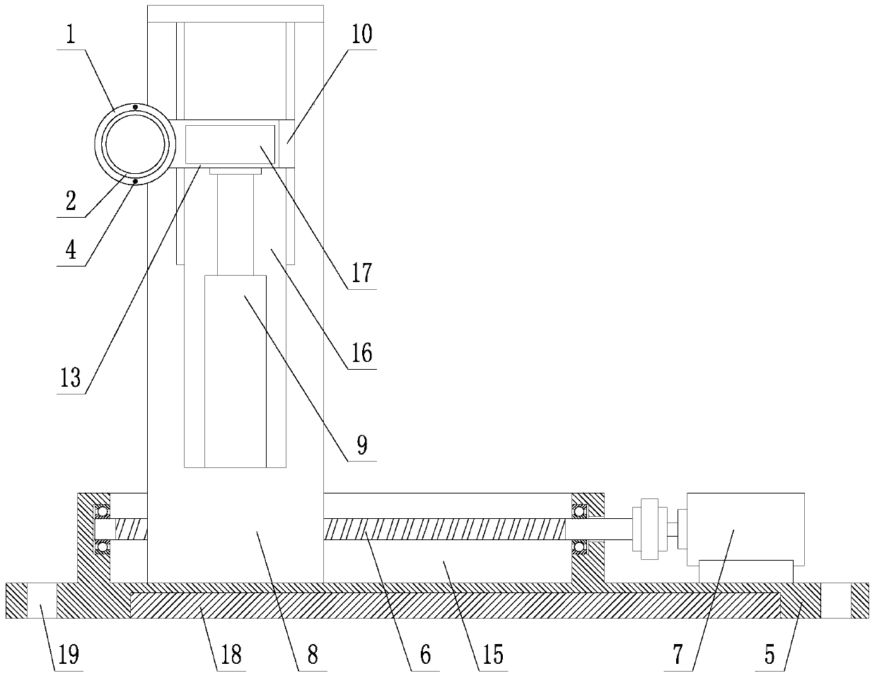
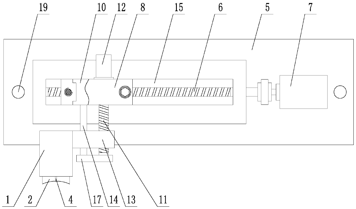
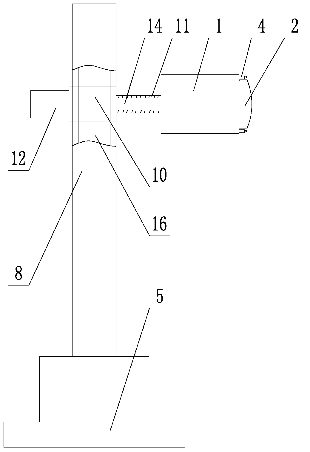
[0020] Such as Figure 1~4 As shown, a high-precision electro-spindle loading mechanism based on piezoelectric ceramics includes a loading assembly and an adjustment assembly. The loading assembly is mounted on the adjustment assembly; the loading assembly includes a reaction force support cylinder 1, a stress loading cylinder 2, and a piezoelectric Ceramic 3; the reaction force support cylinder 1 is sleeved outside the stress loading cylinder 2, and the stress loading cylinder 2 has axial movement freedom in the reaction force support cylinder 1; the piezoelectric ceramic 3 is connected to the reaction force support cylinder 1 Between the inner bottom surface and the outer surface of the bottom of the stress loading cylinder 2; the mouth of the stress loading cylinder 2 adopts a curved surface structure, and the curvature of the mouth of the stress lo...


PUM


Abstract

A piezoelectric ceramic-based high-precision electric spindle loading mechanism comprises a loading component and an adjusting component, the loading component is arranged on the adjusting component,the loading component comprises counter force supporting cylinders, a plurality of stress loading cylinders and a plurality of piezoelectric ceramics; each stress loading cylinder is externally sleeved with the counter force supporting cylinder, and each stress loading cylinder has an axial movement degree of freedom in the counter force supporting cylinder; each piezoelectric ceramic is connectedbetween the inner surface of the bottom of the counter force supporting cylinder and the outer surface of the bottom of the stress loading cylinder; the cylinder opening of each stress loading cylinder adopts an arc surface structure, the radian of the cylinder opening of the stress loading cylinder is the same as the radian of the outer surface of an electric spindle to be tested, the pluralityof piezoelectric ceramics are arranged between the inner surface of the bottom of the counter force supporting cylinder and the outer surface of the bottom of the stress loading cylinder, a stress sensor is arranged on the cylinder opening of the counter force supporting cylinder, the stress sensor is in contact fit with the outer surface of the electric spindle to be tested, and the radians of the cylinder openings of the plurality of stress loading cylinders are different.

Description

Technical field [0001] The invention belongs to the technical field of electric spindle performance testing, and particularly relates to a high-precision electric spindle loading mechanism based on piezoelectric ceramics. Background technique [0002] The electric spindle is the axis that drives the workpiece or the tool to rotate in a CNC machine tool. It usually consists of a lubrication system, a bearing system, a stator and rotor system, and a cooling system. As a key component of the CNC machine tool, the dynamic performance of the electric spindle will directly affect the high-speed machining accuracy. And processing efficiency. [0003] In order to obtain the dynamic performance of the electro-spindle, it is necessary to perform a performance test on the electro-spindle, which includes a loading test on the rotating motor shaft. Through the loading test, the dynamic performance parameters of the electro-spindle under various operating conditions can be obtained, which can re...

Claims


Application Information

Patent Timeline
Patent Type & Authority Patents(China)
IPC IPC(8): G01M13/00
CPCG01M13/00
Inventor 吴玉厚张珂王子男张丽秀夏忠贤闫海鹏高龙飞
Owner SHENYANG JIANZHU UNIVERSITY
Why Eureka
Try Eureka