Permanent magnet motor rotor punching sheet with high reluctance torque

A technology of rotor punching and permanent magnet motor, which is applied in the direction of motor, magnetic circuit, electric components, etc., can solve the problem that the double-one structure cannot be flexible in the adjustment of the magnetic circuit structure, the permanent magnet magnetization effect is not good, and the torque density of the motor is reduced. and other problems, to achieve the effect of improving NVH performance, improving saliency rate and weak field speed expansion ability, and improving torque ripple

Pending Publication Date: 2022-08-09
河南通宇新源动力有限公司
View PDF1 Cites 0 Cited by
  • Summary
  • Abstract
  • Description
  • Claims
  • Application Information

AI Technical Summary

Problems solved by technology

This patent adopts a dual-type topology with a simple structure and process, but the magnetization effect of the permanent magnet is not good, and the quadrature-axis loop channel of the armature reaction is single, which is not conducive to the improvement of the reluctance torque and reduces the torque density of the motor.
Moreover, its double-one structure cannot flexibly adjust the magnetic circuit structure, which also affects the number of magnetic isolation bridges inside the punch, which limits the maximum speed of the rotor.

Method used


Image

  • Permanent magnet motor rotor punching sheet with high reluctance torque
  • Permanent magnet motor rotor punching sheet with high reluctance torque
  • Permanent magnet motor rotor punching sheet with high reluctance torque

Examples


Embodiment Construction

[0031] The present invention will be described in detail below with reference to the accompanying drawings and embodiments.

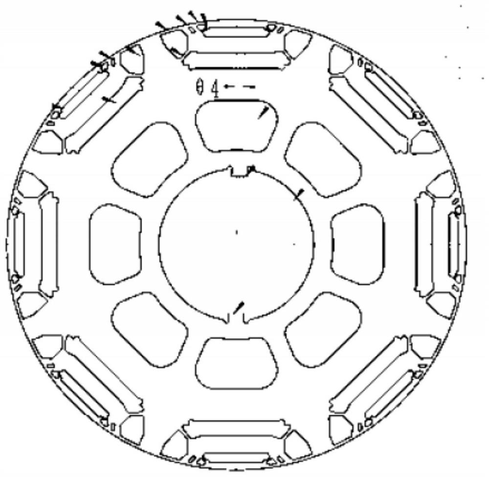
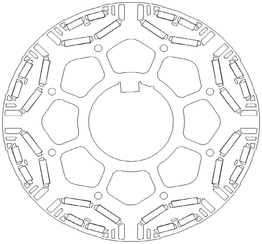
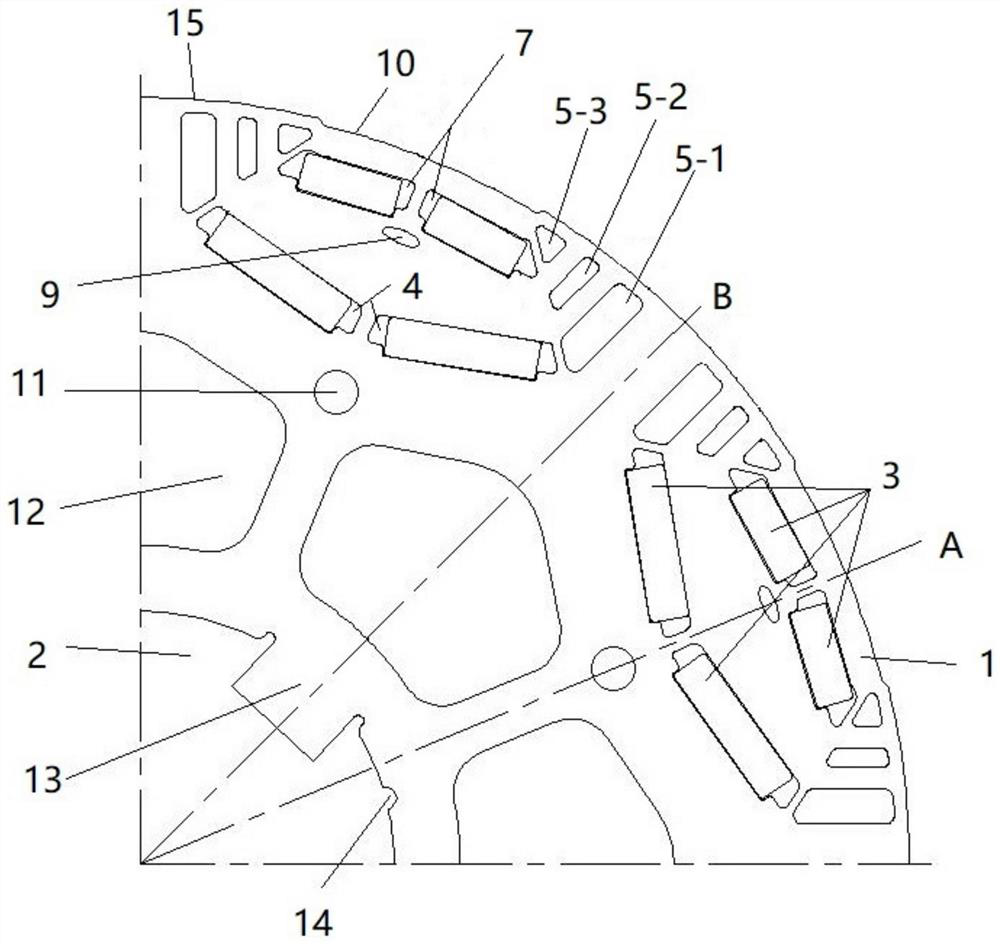
[0032] refer to Figure 2 to Figure 10 As shown, a permanent magnet motor rotor punch with high reluctance torque includes a rotor punch body 1 and a shaft hole 2 located in the center of the rotor punch body. The rotor punch body is divided into several unit magnetic poles. There are several magnetic steel groove groups on the magnetic pole, and the magnetic steel groove group includes a first V-shaped magnetic steel groove 4 symmetrically arranged about the center line A of the d-axis; A magnetic isolation hole 5-1, a second magnetic isolation hole 5-2, and a third magnetic isolation hole 5-3, the first, second and third magnetic isolation holes are arranged parallel to each other and spaced apart. The distances between the second and third magnetic isolation holes and the center line of the d-axis are from far to near; the outer edges of the first, ...


PUM


Abstract

The invention discloses a permanent magnet motor rotor punching sheet with high reluctance torque, which comprises a rotor punching sheet body and a shaft hole, and comprises first V-shaped magnetic steel grooves which are symmetrically distributed relative to the central line of a d shaft, first, second and third magnetic isolation holes are formed in the two ends of each magnetic steel groove group, the outer side lines, away from the shaft hole, of the first, second and third magnetic isolation holes are located on the same circle, and the inner side lines, close to the shaft hole, of the first, second and third magnetic isolation holes are located on the same straight line; third magnetic isolation bridges are arranged between the first magnetic isolation holes and the first V-shaped magnetic steel grooves at equal intervals, and the intersection points of the side lines, close to the second magnetic isolation holes, of the first magnetic isolation holes and the outer side lines, close to the outer circle of the rotor punching sheet, of the first V-shaped magnetic steel grooves are located on the center lines of the third magnetic isolation bridges. The first, second and third magnetic isolation holes are added, and a large number of magnetic isolation bridges are added, so that the mechanical performance of the rotor during high-speed operation can be improved, the high speed of the motor is facilitated, the torque density of the motor is increased, and the speed regulation performance of the motor is improved.

Description

technical field [0001] The invention relates to the technical field of motors, in particular to a permanent magnet motor rotor punching piece with high reluctance torque. Background technique [0002] Chinese patent CN113949183A discloses a rotor punch, rotor and motor, such as figure 1 shown, in which a case of punching with a dual-type structure is proposed. The patent adopts the double-one topology, the structure and process are simple, but the magnetization effect of the permanent magnet is not good, and the armature reaction quadrature loop channel is single, which is not conducive to the improvement of the reluctance torque and reduces the torque density of the motor. In addition, the double-one structure cannot flexibly adjust the magnetic circuit structure, which also affects the number of magnetic isolation bridges inside the punching sheet, so that the maximum rotational speed of the rotor has certain limitations. SUMMARY OF THE INVENTION [0003] In view of th...

Claims


Application Information

Patent Timeline
Patent Type & Authority Applications(China)
IPC IPC(8): H02K1/278H02K1/276H02K1/12H02K11/01
CPCH02K1/278H02K1/2766H02K1/12H02K11/012Y02T10/64
Inventor 梁德志钟运平杨国威陈兆辉刘奇寿张梓梁
Owner 河南通宇新源动力有限公司
Why Eureka
Try Eureka