Permanent magnet motor concentrated winding modulation method and adjustable winding

A technology of concentrated winding and modulation method, which is applied to the shape/style/structure of winding conductors, windings, electric components, etc., can solve the problems of large winding coil width, long winding end length, and increased winding copper consumption. Small motor volume, improved salient pole rate, and improved magnetic circuit asymmetry

Inactive Publication Date: 2020-07-31
SHENYANG POLYTECHNIC UNIV +1
View PDF6 Cites 1 Cited by
  • Summary
  • Abstract
  • Description
  • Claims
  • Application Information

AI Technical Summary

Problems solved by technology

The coil width of the winding is too large, the end of the winding is too large, the copper consumption of the winding is increased, and the advantage of the centralized winding with a similar number of pole slots is lost

Method used


Image

  • Permanent magnet motor concentrated winding modulation method and adjustable winding
  • Permanent magnet motor concentrated winding modulation method and adjustable winding
  • Permanent magnet motor concentrated winding modulation method and adjustable winding

Examples


Embodiment Construction

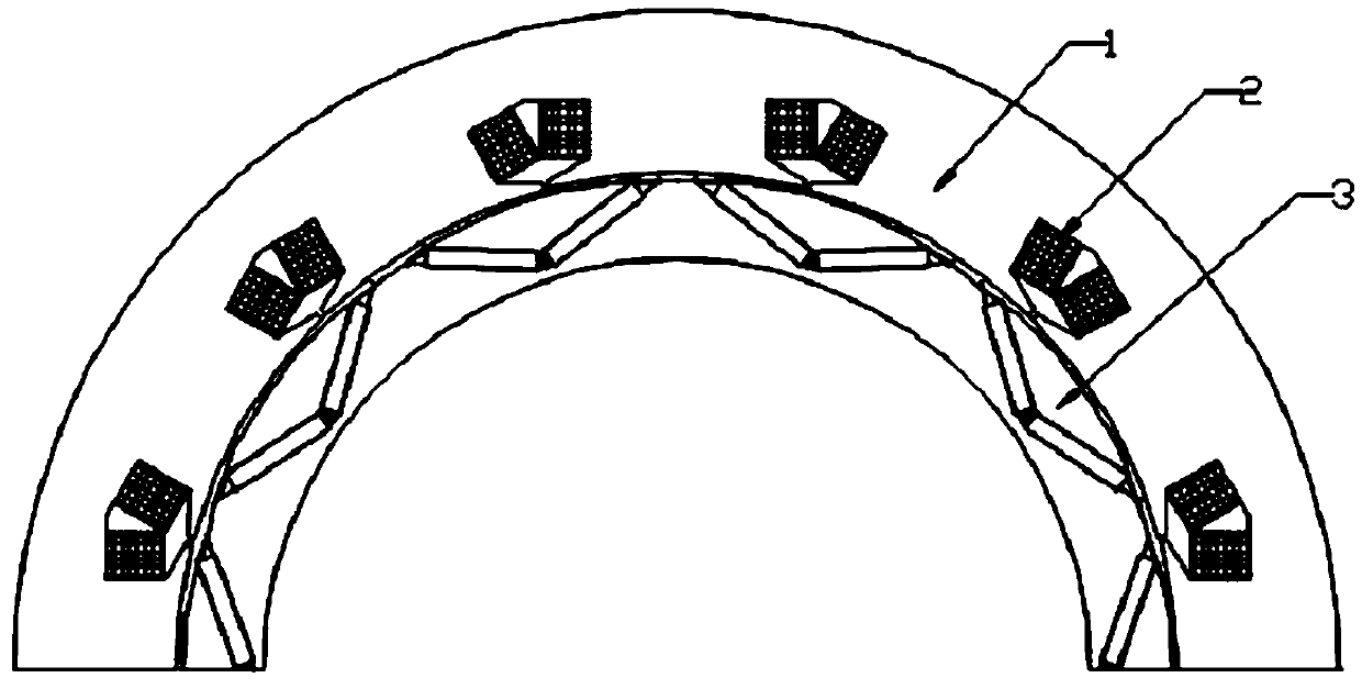
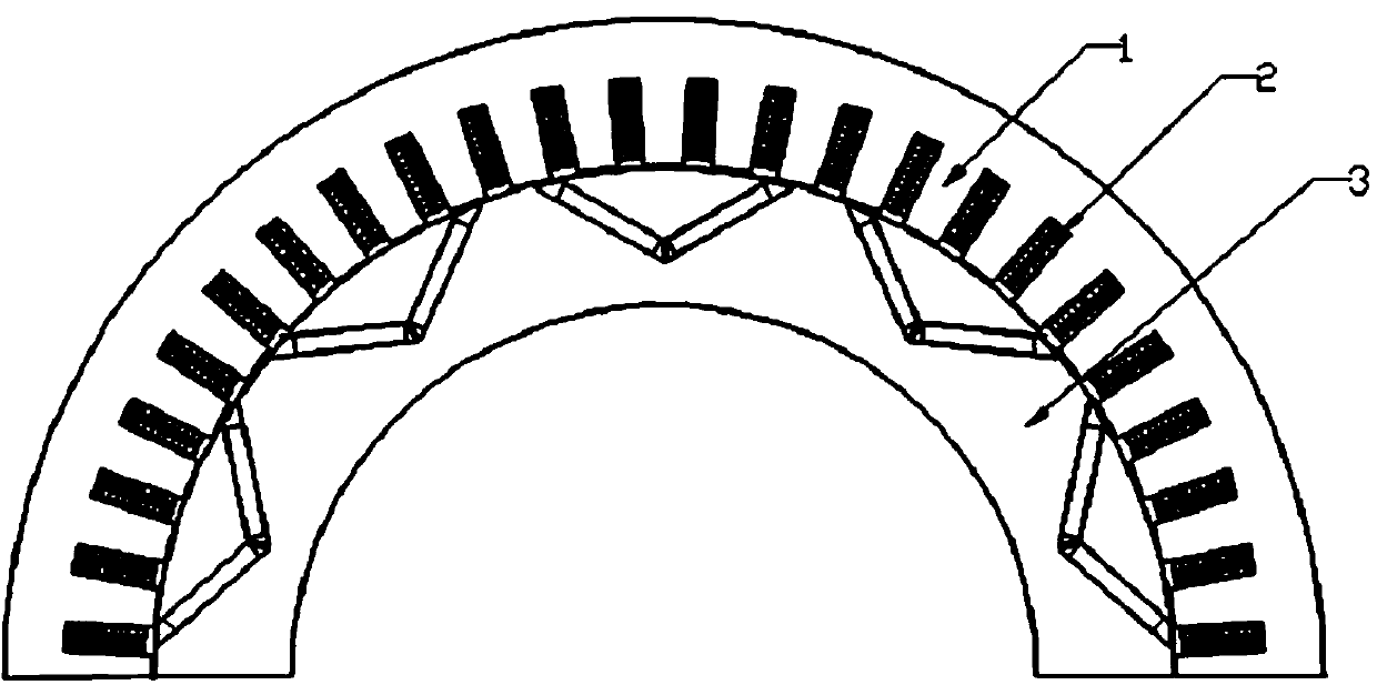
[0043] Modulated concentrated winding of permanent magnet motor. It is characterized in that each phase winding is composed of several coils wound on one tooth in series and in parallel according to a certain connection rule. Each coil is wound on a stator tooth. Single-layer or double-layer armature windings are placed in the stator slots. There is an air gap between the stator and the rotor. The permanent magnetic field provided by the rotor poles is coupled with the rotating magnetic field of the stator armature winding in the air gap, thereby realizing the conversion of electrical energy into mechanical energy.

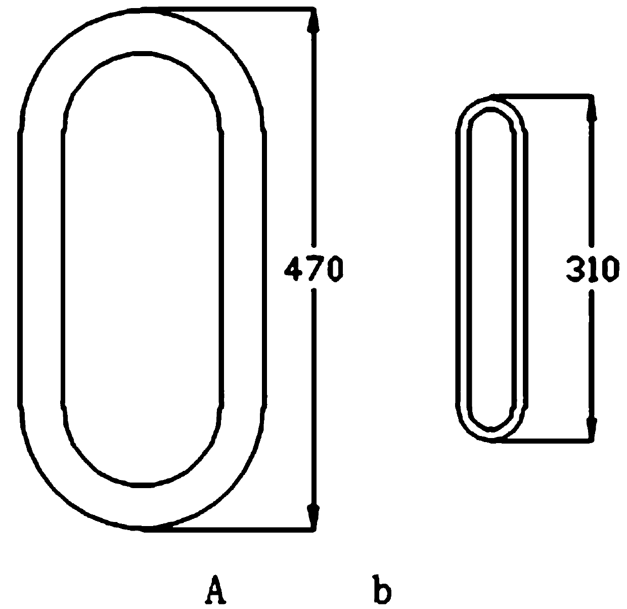
[0044] Such as Figure 1-12 Shown, the present invention will be further described below in conjunction with accompanying drawing:

[0045] The invention provides a concentrated winding, which can realize various numbers of armature poles under the selection of various numbers of stator slots. The modulation function can be realized, and the modulation ratio ...


PUM


Abstract

The invention belongs to the field of motor design, and particularly relates to an armature winding design technology of a permanent magnet motor. Each phase of the windings provided by the inventionrealizes flexible armature magnetic field pole number change through the mutual offset effect of the coils wound on each tooth. According to the scheme, each coil is wound on a stator tooth, each phase winding is formed by connecting a plurality of coils wound on one tooth in series and in parallel according to a certain connection rule, and no matter how many rotor magnetic poles are, the windingcan always keep a single-tooth-winding centralized winding with the pitch of 1.

Description

technical field [0001] The invention belongs to the field of motor design, and in particular relates to the armature winding design technology of a permanent magnet motor. Background technique [0002] Permanent magnet motors are widely used for their flexibility, high efficiency and energy saving. In many fields, it replaces the asynchronous motor or DC motor and its traditional deceleration or speed-up mechanism, realizes direct drive, and improves the efficiency of the transmission system. With the expansion of the application field of permanent magnet motors, it is required that permanent magnet motors must adapt to different installation sizes while meeting various speed and torque requirements. For example, in this type of inner rotor permanent magnet motor with low speed and high torque, the inner diameter of the rotor is sometimes required to cooperate with other devices, so a larger size is required, which results in the structure of this type of motor actually bei...

Claims


Application Information

Patent Timeline
Patent Type & Authority Applications(China)
IPC IPC(8): H02K21/02H02K1/14H02K1/16H02K3/28H02K3/52
CPCH02K21/02H02K1/146H02K1/16H02K3/28H02K3/522H02K2213/03
Inventor 安跃军孙宁邓文宇齐丽君李明韩颖杨霞
Owner SHENYANG POLYTECHNIC UNIV
Why Eureka
Try Eureka