Rotary electric machine control system and rotary electric machine control method

A technology for rotating electrical machines and control systems, applied in control systems, vector control systems, motor generator control, etc., to achieve the effect of increasing rotor torque and increasing reluctance torque

Inactive Publication Date: 2015-04-01
TOYOTA JIDOSHA KK
View PDF1 Cites 1 Cited by
  • Summary
  • Abstract
  • Description
  • Claims
  • Application Information

AI Technical Summary

Problems solved by technology

With this configuration, it is possible to increase the rotor torque on which the current pulse is superimposed without excessively increasing the stator cur

Method used


Image

  • Rotary electric machine control system and rotary electric machine control method
  • Rotary electric machine control system and rotary electric machine control method
  • Rotary electric machine control system and rotary electric machine control method

Examples


Embodiment Construction

[0022] Embodiments of the present invention will be described below with reference to the drawings. In the following description, a rotary electric machine functions as a motor generator, and is used as a driving source of a hybrid vehicle. This is only illustrative, and the rotary electric machine can also be used as a drive source of another electric vehicle such as an electric car. Furthermore, a rotating electric machine can function only as a motor, or only as a generator. In addition, the same reference numerals denote the same components throughout the drawings.

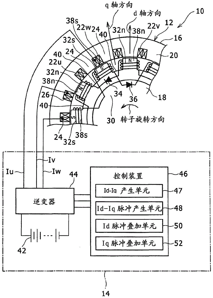
[0023] figure 1 is a view showing the rotary electric machine control system 10 according to the present embodiment, and is also a view showing a partial section in the circumferential direction of the rotary electric machine 12 and the configuration of the rotary electric machine drive unit 14 . The rotary electric machine control system 10 includes a rotary electric machine 12 and a rotary electric machin...


PUM


Abstract

A rotary electric machine control system includes a control device that controls a rotary electric machine. When there is a current phase at which a reluctance torque is maximum between a first current phase (theta 1) of a first current vector (I1) on which current pulses have not been superimposed yet and a second current phase (theta 2) of a second current vector (I2) obtained by increasing a d-axis current and reducing a q-axis current, the control device sets an intermediate current vector (Im) having an intermediate phase (theta m) between the first and second current phases (theta 1, theta 2). The intermediate current vector (Im) is set so as to be larger than an imaginary current vector (Ima) at the intermediate phase (theta m) in the case where a vector locus is varied in a straight line from the first current vector (I1) to the second current vector (I2). The current pulses are generated by changing the current vector in order of I1, Im and I2 and returning the current vector in order of Im and I1.

Description

technical field [0001] The present invention relates to a rotating electrical machine control system and a rotating electrical machine control method, and more particularly, the present invention relates to control in the case of superimposing a current pulse on a current vector. Background technique [0002] Japanese Patent Application Publication No. 2011-41433 (JP 2011-41433A) describes a control device for an electromagnetic rotating electrical machine. A rotating electrical machine includes a stator that generates a rotating magnetic field and a rotor that faces the stator and rotates. The rotor includes rotor coils and diodes each short-circuited with the rotor coils in a selected polarity. In the control device, when predetermined conditions are satisfied, current pulses are superimposed on the stator currents respectively flowing through the stator coils. [0003] In the rotating electrical machine described in JP 2011-41433A, a method of superimposing current puls...

Claims


Application Information

Patent Timeline
IPC IPC(8): H02P21/00H02K19/12H02K19/28H02K21/04H02P25/02H02P25/08H02P21/12H02P25/03H02P27/04
CPCH02K19/12H02P21/22H02P25/03H02P25/08H02P21/20
Inventor 山田英治平本健二
Owner TOYOTA JIDOSHA KK
Why Eureka
Try Eureka