

Connecting structure and plunger pump
A connection structure and plunger technology, which is applied to pump components, variable displacement pump parts, parts of pumping devices for elastic fluids, etc., and can solve the problems of easy wear and looseness of plungers and pull rods
- Summary
- Abstract
- Description
- Claims
- Application Information
AI Technical Summary
Problems solved by technology
Method used
Image

Examples
Embodiment Construction
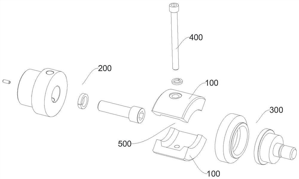
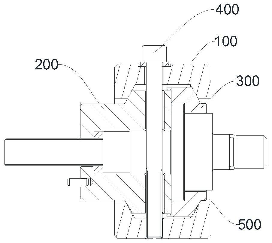
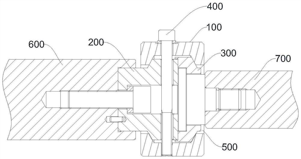
[0037] Embodiments of the present application will be described in detail below in conjunction with the accompanying drawings.
[0038] In the description of the present application, it should be understood that the orientation or positional relationship indicated by the terms "upper", "bottom", "inner", "outer", etc. is based on the orientation or positional relationship shown in the drawings, and is only for the purpose of It is convenient to describe the application and simplify the description, but not to indicate or imply that the device or element referred to must have a specific orientation, be constructed and operate in a specific orientation, and thus should not be construed as limiting the application.
[0039] The terms "first" and "second" are used for descriptive purposes only, and cannot be understood as indicating or implying relative importance or implicitly specifying the quantity of indicated technical features. Thus, a feature defined as "first" and "second"...
PUM
 Abstract
Description
Claims
Application Information