

Heat exchange devices for motors and their shafting, wind turbines
A technology for wind turbines and heat exchange devices, which is applied in wind turbine combinations, wind turbines, wind energy power generation, etc., can solve the problems of difficulty in dissipating heat and no cooling scheme for generators, and achieves the effect of good cooling effect.
- Summary
- Abstract
- Description
- Claims
- Application Information
AI Technical Summary
Problems solved by technology
Method used
Image

Examples
Embodiment Construction
[0067] In order to enable those skilled in the art to better understand the technical solutions of the present invention, the present invention will be further described in detail below in conjunction with the accompanying drawings and specific embodiments.
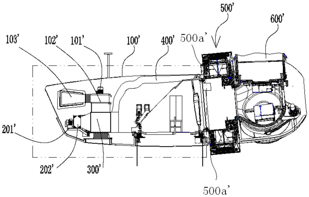
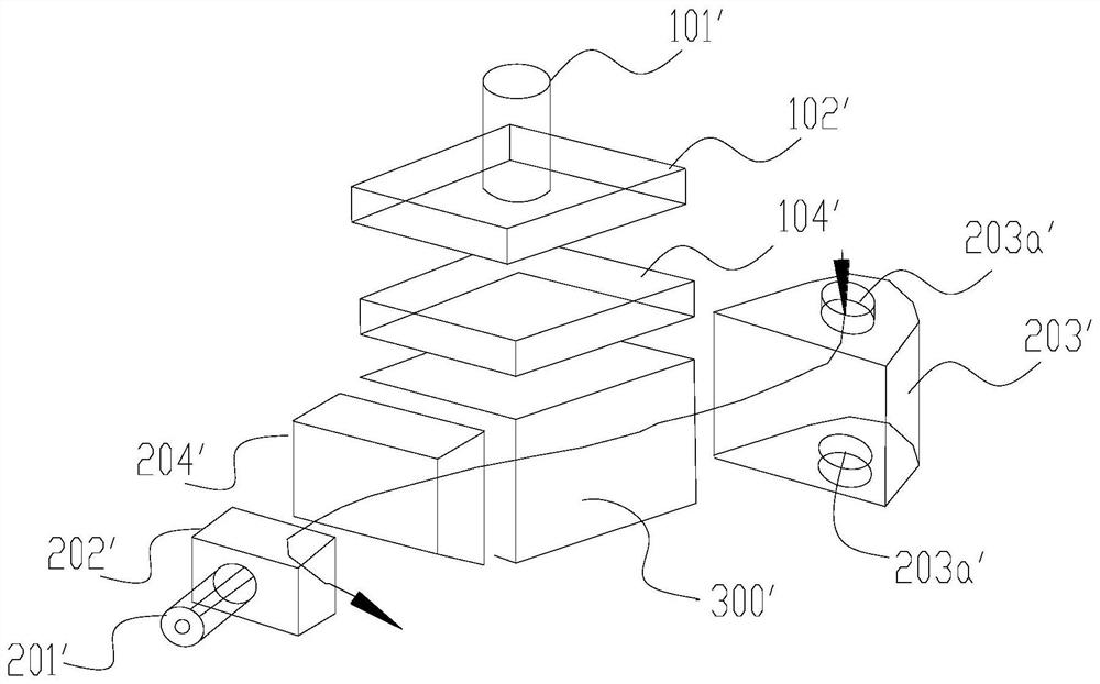
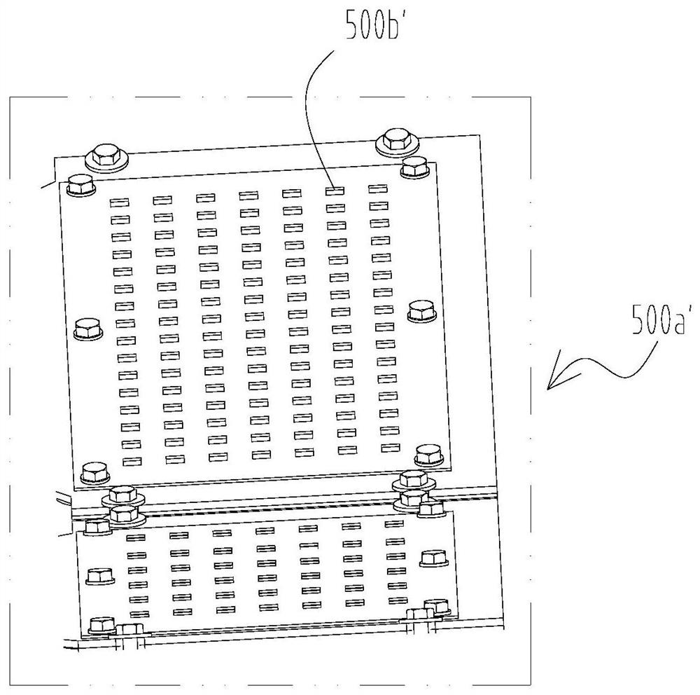
[0068] Please refer to Figure 4-6 , Figure 4 It is a schematic diagram of a specific embodiment of the power generation equipment provided by the present invention; Figure 5 for Figure 4 Schematic diagram of the generator in middle, showing the internal structure; Image 6 for Figure 5 Partial enlarged schematic diagram of the middle I site.
[0069] In this embodiment, wind power generation equipment is taken as an example, the wind power generation equipment includes a generator 200, the left end of the generator 200 is provided with a nacelle 100, and the right end is provided with a hub 500 and an impeller. Such as Figure 5 As shown, the generator 200 includes a motor fixed shaft 201 , which is in the shap...
PUM
 Abstract
Description
Claims
Application Information