Method for extracting inherent frequency difference between blades by single or uniformly distributed blade end timing sensor
A natural frequency, sensor technology, applied in the testing of instruments, machines/structural components, the use of sonic/ultrasonic/infrasonic waves to analyze solids, etc., can solve problems such as increased measurement costs, large errors, and inability to achieve online real-time detection and diagnosis, etc. Achieve real-time health monitoring, fast and stable computing
Active Publication Date: 2021-10-22
XI AN JIAOTONG UNIV
View PDF8 Cites 0 Cited by
- Summary
- Abstract
- Description
- Claims
- Application Information
AI Technical Summary
Problems solved by technology
In the actual use of the tip timing measurement method, multiple tip timing sensors are often used to reduce the aliasing effect caused by undersampling, but the installation of multiple tip timing sensors in the actual limited space will cause greater trouble , and it also increases the measurement cost. Traditional methods, such as c
Method used
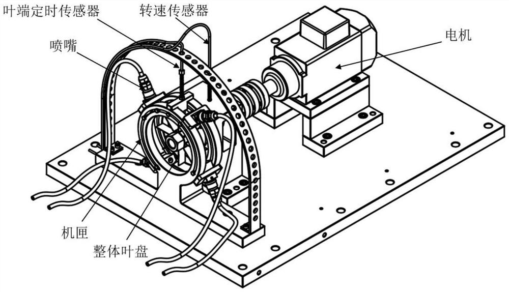
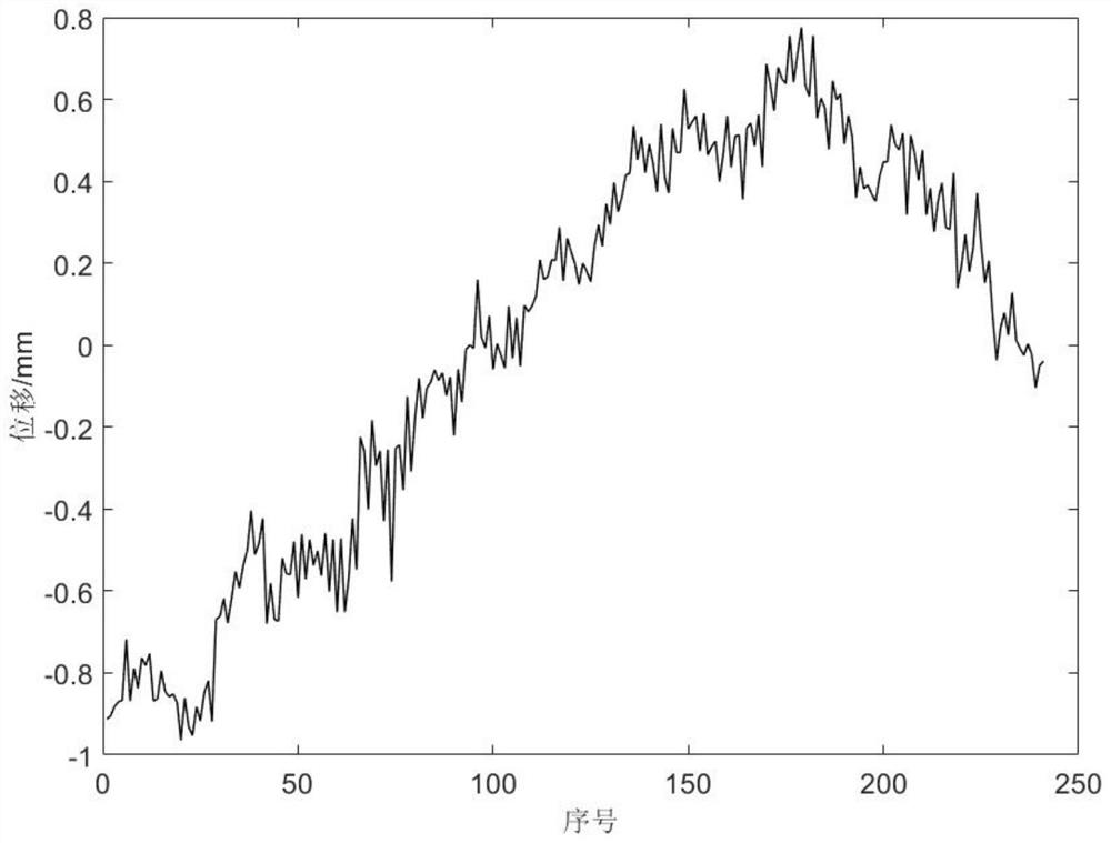
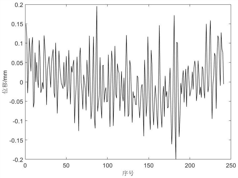
View moreImage
Smart ImageViewing Examples
Examples
 PUM
| Property | Measurement | Unit |
|---|---|---|
| Radius | aaaaa | aaaaa |
Abstract
The invention discloses a method for extracting an inherent frequency difference value between blades by a single or uniformly distributed blade end timing sensor. The method comprises the following steps: acquiring the actual arrival time of a rotating blade by using a single blade end timing sensor or uniformly distributed blade end timing sensors; converting the difference between the theoretical arrival time and the actual arrival time into displacement data of the blade end according to the rotating speed and the blade length of the rotating blade; selecting displacement data of blade ends of two rotating blades with the same blade length at the same rotating speed; intercepting displacement data and respectively carrying out discrete Fourier transform, wherein the sampling frequency is approximate to the average rotating speed to obtain frequency spectrum data; and respectively extracting corresponding frequency remainders after aliasing the inherent frequencies of the two blades from the frequency spectrum data, and subtracting the two frequency remainders to obtain the inherent frequency difference between the two blades.
Description
technical field [0001] The invention belongs to the field of non-contact non-destructive detection of blades, in particular to a method for extracting natural frequency difference between blades by a single or evenly distributed blade end timing sensor. Background technique [0002] Rotor blades are key components of large-scale equipment such as gas turbines and aeroengines. They often rotate at high speed under high temperature and high pressure conditions, and are subjected to cyclic alternating loads and dynamic loads such as centrifugal force and aerodynamic force. vibration. Statistical data show that blade damage accidents account for about one-third of the total structural failures of gas turbines, so it is necessary to perform fault detection on rotor blades. However, the traditional contact blade vibration measurement method, such as the strain gauge measurement method, needs to be shut down and it is difficult to monitor the vibration of all blades, and the blade...
Claims
Login to View More Application Information
Patent Timeline
 IPC IPC(8): G01N29/12G01N29/44G01M13/00G01H17/00G06F17/14
CPCG01N29/12G01N29/44G01M13/00G01H17/00G06F17/141
Inventor 杨志勃曹佳辉陈雪峰王增坤杨来浩田绍华李浩琪李文博
Owner XI AN JIAOTONG UNIV
Features
- R&D
- Intellectual Property
- Life Sciences
- Materials
- Tech Scout
- Unparalleled Data Quality
- Higher Quality Content
- 60% Fewer Hallucinations
Learn More Browse by: Latest US Patents, China's latest patents, Technical Efficacy Thesaurus, Application Domain, Technology Topic, Popular Technical Reports.
© 2025 PatSnap. All rights reserved.Legal|Privacy policy|Modern Slavery Act Transparency Statement|Sitemap|About US| Contact US: help@patsnap.com


