
Automatic cleaning nozzle

An automatic cleaning and nozzle technology, applied in the direction of spraying device, spraying device, etc., can solve the problems of wasting water and energy, affecting the spraying effect, nozzle turbulence, etc., to achieve the effect of saving space, simple structure and reducing parts

Pending Publication Date: 2021-10-26
苏州麦风环保科技有限公司
View PDF12 Cites 0 Cited by
  • Summary
  • Abstract
  • Description
  • Claims
  • Application Information

AI Technical Summary

Problems solved by technology

[0007] In view of the above-mentioned shortcomings of the prior art, the purpose of the present invention is to provide an automatic cleaning nozzle, which is used to solve the shortcomings of the nozzle in the prior art: when in use, the spray angle is controlled by the body to block the internal turbulent flow of the nozzle, which affects the spray effect ; Need more water and higher pressure to meet the demand, wasting water and energy; nozzles are mainly used in water that does not contain or contain tiny solid impurities. With the improvement of environmental protection requirements, especially the increase in the cost of clean water, more and more When the factory starts to circulate water, when the recycled water carries impurities, the impurities will accumulate and block between the guide core and the nozzle core; in the case of shutting down the spray, it is necessary to add an on-off valve in front of the nozzle

Method used


Image

  • Automatic cleaning nozzle
  • Automatic cleaning nozzle
  • Automatic cleaning nozzle

Examples


Embodiment Construction

[0030] The implementation of the present invention will be illustrated by specific specific examples below, and those skilled in the art can easily understand other advantages and effects of the present invention from the contents disclosed in this specification.

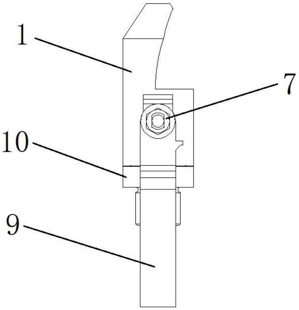
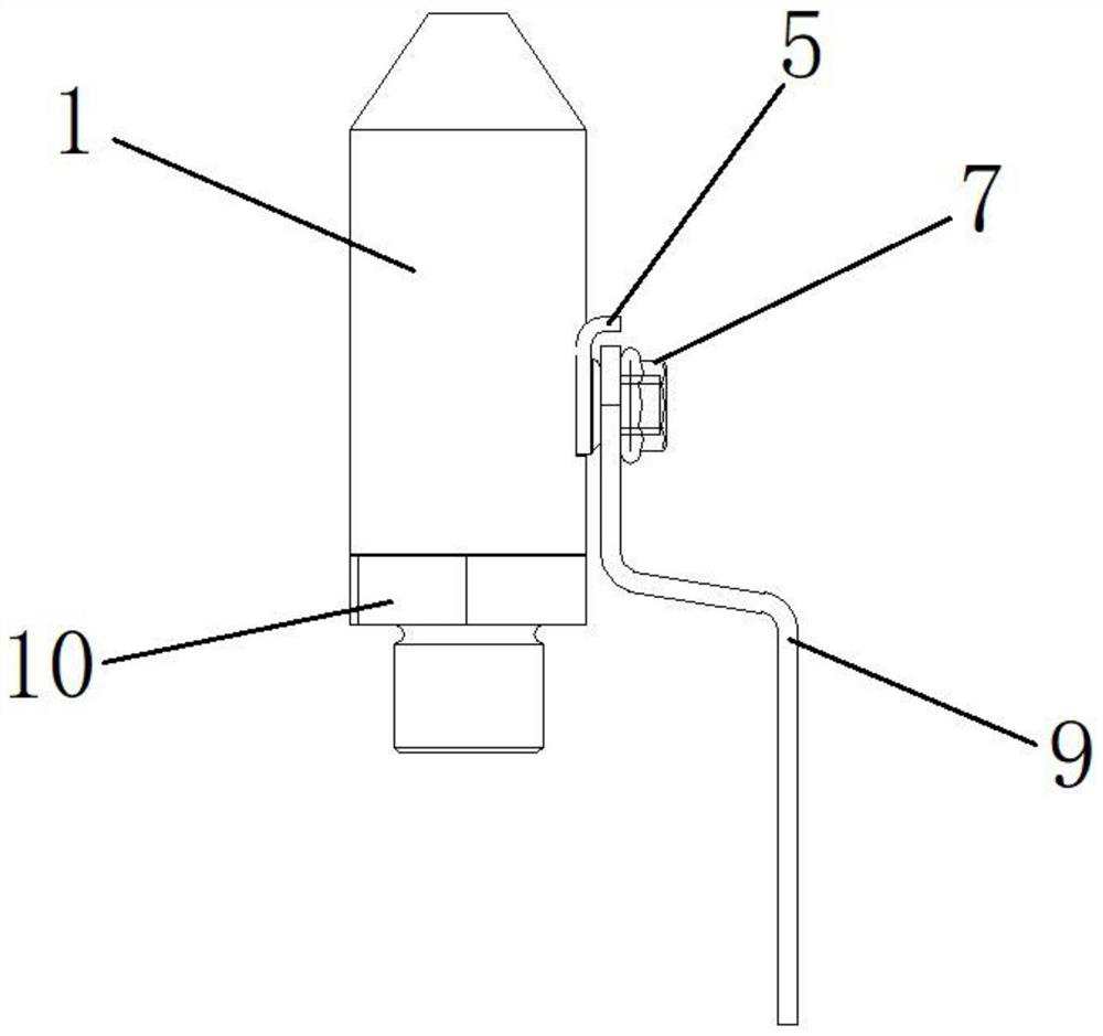
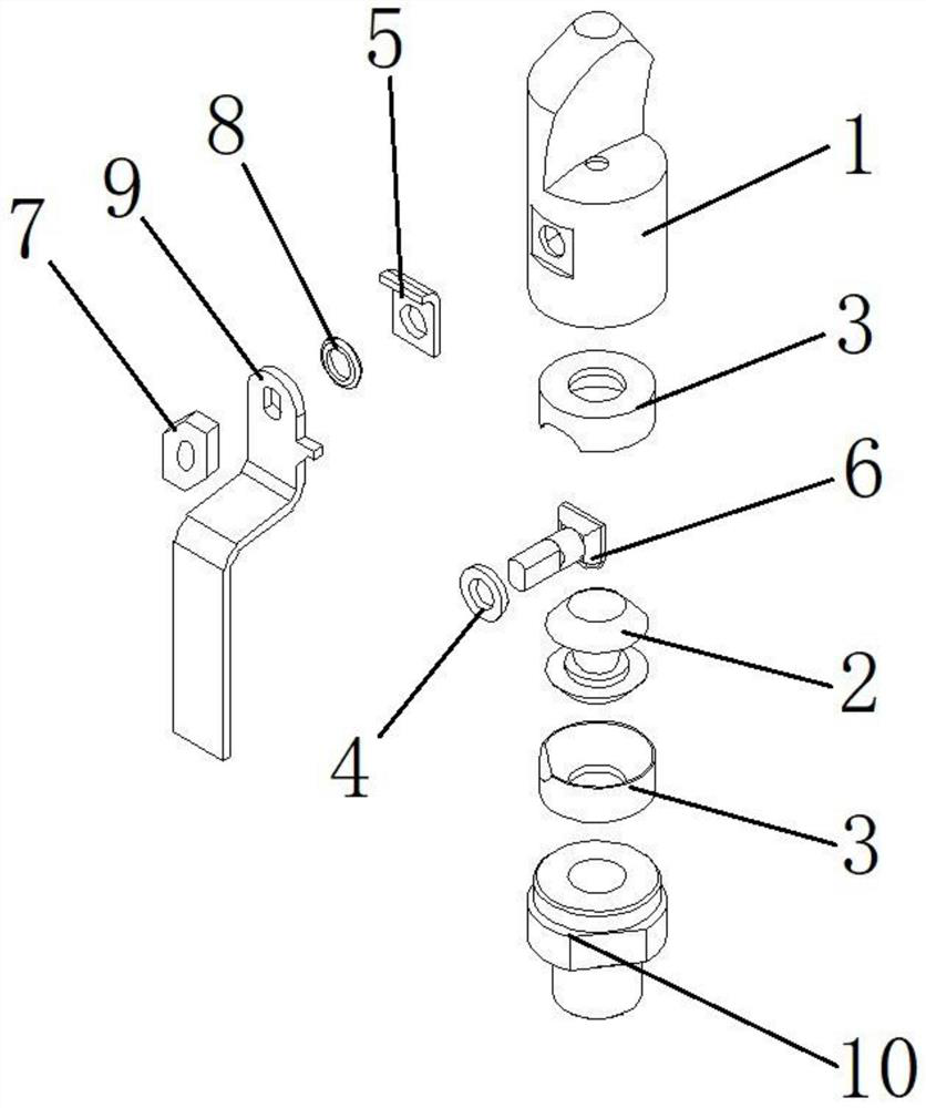
[0031] see Figure 1 to Figure 3 . It should be noted that the structures, proportions, sizes, etc. shown in the drawings attached to this specification are only used to match the content disclosed in the specification, for those who are familiar with this technology to understand and read, and are not used to limit the implementation of the present invention. Limiting conditions, so there is no technical substantive meaning, any modification of structure, change of proportional relationship or adjustment of size, without affecting the effect and purpose of the present invention, should still fall within the scope of the present invention. The disclosed technical content must be within the scope covered. At the sa...


PUM


Abstract

The invention provides an automatic cleaning nozzle, and belongs to the technical field of special nozzles. The automatic cleaning nozzle comprises a flow guide valve body, an injection valve element and a multi-position handle, the flow guide end of the flow guide valve body is conical and provided with an arc-shaped flow guide weir, and a cavity is formed in the valve body and used for assembling the valve element; the injection valve element is a spherical valve element, a conical inner hole is formed in the injection valve element, sealing rings are arranged at the upper end and the lower end of the valve element and sleeve the outer side surface of the valve element, and an annular groove is formed in the outer side surface of the valve element and used for assembling a connecting rod; and the multi-position handle is arranged on the surface of one side of the flow guide valve body and fixed to the upper end of the connecting rod through a self-locking nut, and the lower end of the connecting rod is connected with the annular groove in the surface of the valve element. The working efficiency of the nozzle is effectively improved, water resources are saved, and the service life is prolonged; and meanwhile, the structure is simple, and operation is easy and convenient.

Description

technical field [0001] The invention relates to an automatic cleaning nozzle, which belongs to the technical field of special nozzles. Background technique [0002] Existing nozzle functional design: the nozzle body is fixed to the point of use, and a certain flow of water passes through the nozzle core to form a columnar water flow; the columnar water flow passes through the diversion core to form a 360-degree, and then blocked by the outlet area of ​​​​the body to form a fan-shaped spray. [0003] Weaknesses and flaws: [0004] Waste of energy and water: When the above-mentioned nozzles are used, they rely on the body to block the spray angle to cause turbulent flow inside the nozzle and affect the spray effect; more water and higher pressure are needed to meet the demand, wasting water and energy; [0005] Easy to clog: The nozzles of the above design are mainly used in water that does not contain or contain tiny solid impurities. With the improvement of environmental pr...

Claims


Application Information

Patent Timeline
IPC IPC(8): B05B1/04B05B1/30B05B1/34B05B12/00B05B15/18B05B15/531B05B15/65
CPCB05B1/04B05B1/3026B05B1/3402B05B12/002B05B15/531B05B15/65B05B15/18
Inventor 汪平保杨红霞
Owner 苏州麦风环保科技有限公司
Features
  • Generate Ideas
  • Intellectual Property
  • Life Sciences
  • Materials
  • Tech Scout
  • Unparalleled Data Quality
  • Higher Quality Content
  • 60% Fewer Hallucinations
Learn More