A kind of filling method of down jacket down material

A filling method and technology for down jackets are applied in the direction of sewing tools, textiles, papermaking, sewing equipment, etc., which can solve the problems of poor effect and low efficiency of down filling methods, and achieve the effect of improving efficiency.

Active Publication Date: 2022-04-01
安徽宜民服饰股份有限公司
View PDF7 Cites 0 Cited by
  • Summary
  • Abstract
  • Description
  • Claims
  • Application Information

AI Technical Summary

Problems solved by technology

[0003] The technical problem to be solved by the present invention is to provide a down jacket filling method to solve the problem of low efficiency and poor effect of down filling methods in the prior art described in the background technology

Method used


Image

  • A kind of filling method of down jacket down material
  • A kind of filling method of down jacket down material
  • A kind of filling method of down jacket down material

Examples


Embodiment 2

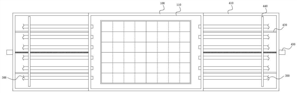
[0065] As an optimized solution of Embodiment 1, the down filling tube moving assembly 400 includes a support frame 410 connected to the side wall of the processing table 100, and a first transverse ball wire is connected between the support frame 410 and the side wall of the processing table 100. The bar module 430 and some first guide rods 420, the first guide rod 420 slides through the moving plate 440, the moving plate 440 is connected with the ball nut of the first ball screw module 430, the first down filling tube 200, The second down filling tube 300 runs through the moving plate 440 and is fixedly connected with the moving plate 440 .

[0066] This embodiment is implemented in such a way that the first ball screw module 430 provided can drive the moving plate 440 to move, and the moving plate 440 drives the first down filling tube 200 and the second down filling tube 300 in the first positioning hole 210, The movement in the second positioning hole 310 , and the first ...

Embodiment 3

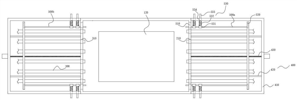
[0068] As an optimization scheme of the second embodiment, the positions corresponding to the first slide bar 500a and the second slide bar 500b on the side wall of the positioning groove 110 are respectively provided with longitudinally distributed moving holes 510, and the moving plate 440 corresponds to the first slide bar 500b. The positions of the rod 500a and the second sliding rod 500b are respectively provided with moving grooves 520 distributed longitudinally, and the ends of the first sliding rod 500a and the second sliding rod 500b are respectively slidably connected to the moving grooves 520 .

[0069] This embodiment is implemented in such a way that the movement of the moving plate 440 can drive the first sliding bar 500a, The second slide bar 500b moves, so that the first slide bar 500a and the second slide bar 500b move simultaneously with the first down filling tube 200 and the second down filling tube 300 to realize synchronous movement.

Embodiment 4

[0071] As an optimized solution of the third embodiment, the elastic tensioning assembly 530 includes a sliding sleeve 531 slidingly sleeved on the first sliding rod 500a or the second sliding rod 500b, and a sliding hole 534 penetrating the support frame 410. The sliding sleeve 531 It is connected with the support frame 510 through the first spring 532 , and the sliding sleeve 531 is provided with a positioning rod 533 , and the positioning rod 533 slides through the first spring 532 and the sliding hole 534 .

[0072] This embodiment is implemented in such a way that the first spring 532 can apply a pulling force to the sliding sleeve 531, so that the sliding sleeve 531 drives the first sliding rod 500a and the second sliding rod 500b to move to the side wall of the support frame 410, because the moving hole 510 and the moving groove 520 are longitudinally distributed, so the first sliding rod 500a and the second sliding rod 500b can move in the moving hole 510 and the moving...


PUM


Abstract

The invention discloses a method for filling down material for down jackets, and relates to the technical field of down jacket processing. The horizontal sewing lines of the down-filled squares on the down quilt are stitched together, and the longitudinal sewing lines of the down-filled squares in the middle of the down quilt are stitched together; Place the down quilt in the positioning groove; then drive the first down-filling tube and the second down-filling tube into the down-filling grid through the down-filling tube moving component, and the elastic tensioning component pulls the first slide bar and the second slide bar , so that the duvet is tightened: then a certain amount of down is poured into the grid through the first down filling tube and the second down filling tube; then the longitudinal moving component and the horizontal moving component cooperate with the lifting component to drive the single head of the arm sewing machine to move, The longitudinal sewing thread of the down-filled grid can be sewn by a single head of multiple arm-type sewing machines; the down-filling of the duvet can be completed by analogy; the present invention has the advantages of convenient use, high down-filling efficiency, and prevention of down-running advantage.

Description

technical field [0001] The invention relates to the technical field of down jacket processing, in particular to a down jacket filling method. Background technique [0002] With the development of society, a large amount of natural resources have been exploited and utilized, resulting in the destruction of the ecology. This year, extreme weather has occurred frequently. In winter, the impact of extreme cold air on the south has gradually deepened. The quilt mainly uses duck down or goose down to keep warm, but the down filling method of the existing down quilt is mainly through semi-automatic manual operation. After the filling is completed, start sewing, and then fill other squares. This filling method is inefficient; Sexual down filling, but in this way there will be a certain phenomenon of running down. Contents of the invention [0003] The technical problem to be solved by the present invention is to provide a down jacket filling method to solve the problems of low e...

Claims


Application Information

Patent Timeline
Patent Type & Authority Patents(China)
IPC IPC(8): B68G7/06A41H43/00D05B73/06
CPCB68G7/06A41H43/00D05B73/06
Inventor 王丽丽张贝贝王雪丽
Owner 安徽宜民服饰股份有限公司
Why Eureka
Try Eureka