The structure of the filling tube for the filling machine

A down filling machine and tube structure technology, applied in the field of down product filling equipment, can solve the problems of affecting down filling speed, affecting down filling efficiency, length extension, etc., achieving a simple overall structure, ensuring down filling efficiency, and easy assembly. Effect

Active Publication Date: 2022-07-29
SUZHOU BIYANGTE CLOTHING EQUIP CO LTD
View PDF15 Cites 0 Cited by
  • Summary
  • Abstract
  • Description
  • Claims
  • Application Information

AI Technical Summary

Problems solved by technology

But this CN104925733A has the following shortcoming: one, owing to a transition pipe is set between the inlet and outlet pipes and a filter screen (annular mesh cover) is provided in the transition lumen of the transition pipe, the When the down passes through the filter screen and enters the down pipe, although a part of the air can be drawn out from the mesh on the filter screen, the exhaust port of the transition pipe and the exhaust pipe in turn, the length from the down inlet to the down outlet is significantly extended, thus To a certain extent, it will also affect the filling speed; secondly, in order to meet the matching requirements for the transition tube with a tee effect, it is necessary to connect the end of the down tube towards the transition tube and the end of the down tube towards the transition tube. The outer wall is processed into and out of the fleece pipe threads respectively, and the transition pipe internal threads are respectively processed on the inner walls of both ends of the transition pipe, so whether it is manufacturing or assembling is all relatively troublesome; third, because the pipe wall of the fleece pipe is If there is no vent hole, it is necessary to install a breathable mesh at the end of the fleece outlet facing the fleece outlet (the two ends of the breathable mesh are respectively fixed on the fleece outlet through the first and second fixing rings). A cavity is formed between the outer walls of the down tube, and the air returned from the down tube leaks out through the cavity, but the air in the down tube passes through the cavity between the aforementioned air mesh and the outer wall of the down tube. When the down leaks out, the down will also enter the cavity along with the return air flow, resulting in blockage of the cavity. If the blockage cannot be unblocked in time, it will easily cause the down tube to bulge and affect the filling efficiency. If the blockage is unblocked, it will increase Additional workload for online workers

Method used


Image

  • The structure of the filling tube for the filling machine
  • The structure of the filling tube for the filling machine

Examples


Embodiment

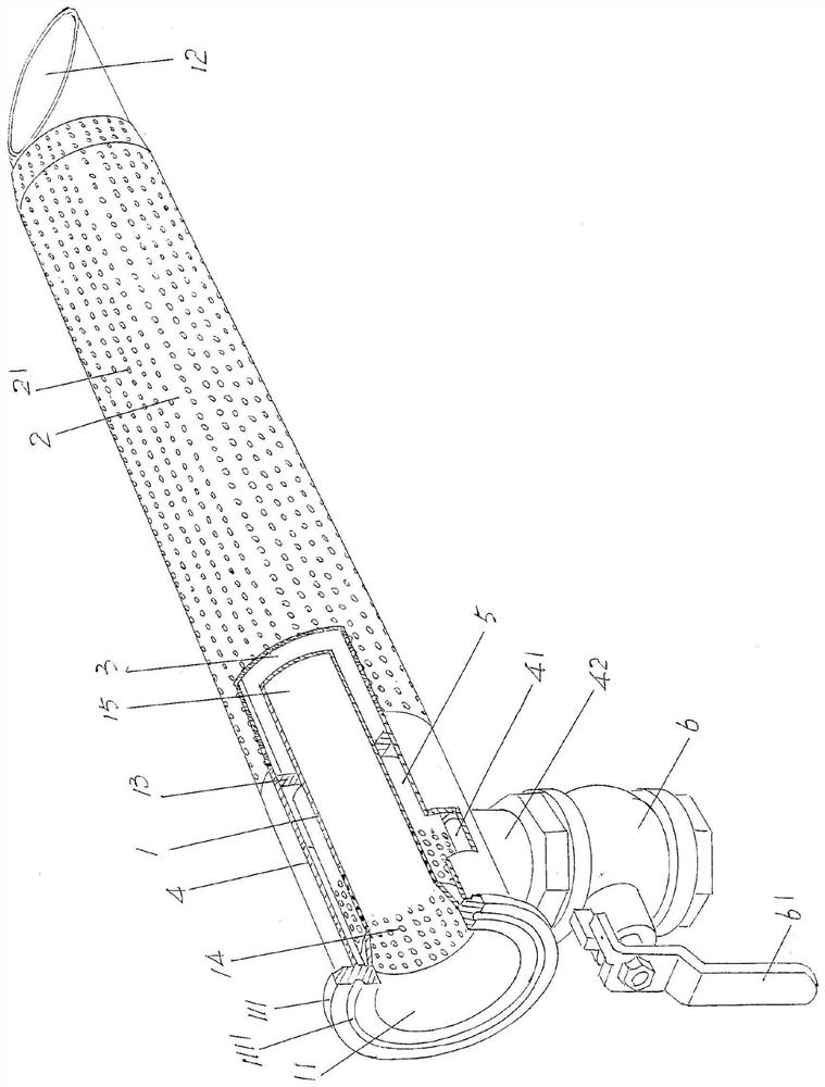
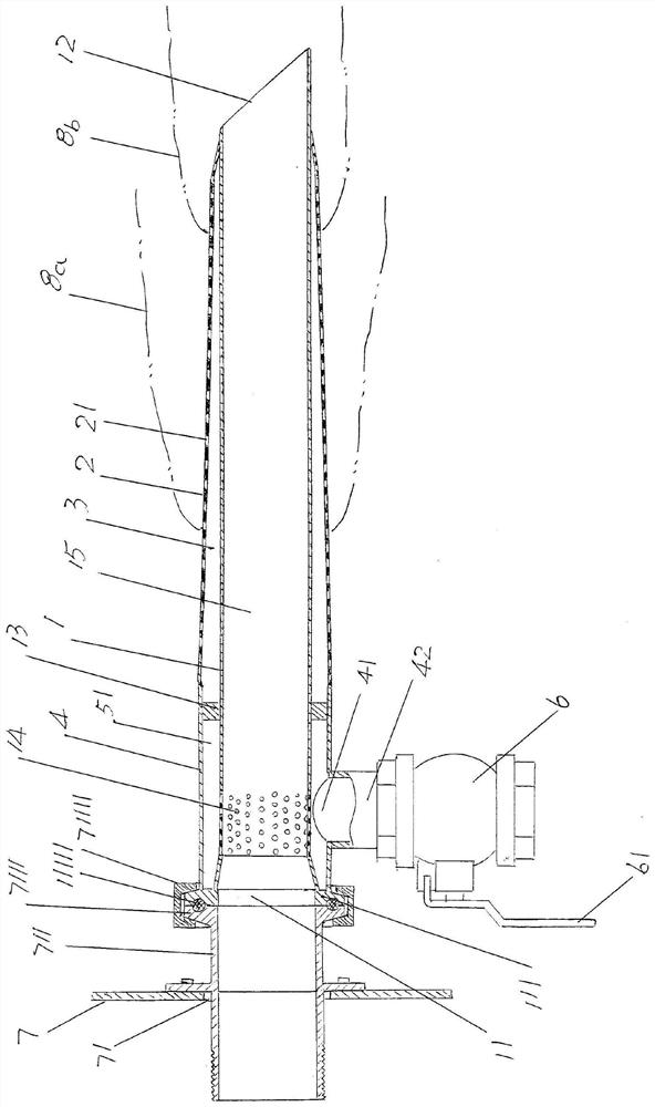
[0024] See figure 1 , shows a fleece tube 1, the left end of the fleece tube 1 is formed with a fleece tube inlet 11, and the right end of the fleece tube 1 is formed with a fleece tube outlet 12; Trachea 2, the exhaust tube 2 is located outside the aforementioned fleece tube 1 and the left end and the right end of the exhaust tube 2 are closed, and an exhaust chamber 3 is formed between the inner wall of the exhaust tube 2 and the outer wall of the fleece tube 1, and the exhaust chamber 3 It communicates with the outside world through the vent hole 21 of the vent tube 2 opened on the vent tube 2 .

[0025] As the technical point of the technical solution provided by the present invention: a spacer 13 is fixed on the outer wall of the aforementioned fleece tube 1 and at a position corresponding to the left end of the aforementioned air deflation tube 2 around the circumferential direction of the fleece tube 1, and on the A pre-deflation cavity sleeve 4 is arranged between the...


PUM


Abstract

A fleece-filling tube structure for a fleece-filling machine, comprising a fleece-passing tube, a fleece-passing tube inlet port at the left end and a fleece-passing tube outlet port at the right end; a venting tube is located outside the fleece-passing tube and the left and right ends are closed, and the ventilating tube is closed. There is a deflation cavity between the inner wall of the trachea and the outer wall of the velvet tube, and the deflation cavity is communicated with the outside world. Features: A spacer is fixed on the outer wall of the velvet tube. The right end face of the pre-deflation chamber sleeve and the left end face of the air deflation pipe are joined to each other at the position of the spacer. The cavities are communicated with each other, a pre-bleed port is arranged on the sleeve of the pre-bleed cavity, the pre-bleed hole is communicated with the pre-bleed cavity and a pre-bleed control valve is arranged, and the pre-bleed cavity and the cavity are separated by a spacer. Avoid the down bobbin bulging, improve the down filling efficiency; avoid the path from the down tube inlet to the down tube outlet too long; the structure is simple; the pre-vent control valve will not be blocked.

Description

technical field [0001] The invention belongs to the technical field of filling equipment for down products, and in particular relates to a down filling tube structure for a down filling machine. Background technique [0002] The aforementioned down products mainly refer to, but are not limited to, down jackets, duvets, down pads, down pillows and even down dolls, etc. When making such products, it is necessary to fill the prefabricated bobbins with down and then seal them to form down. product. [0003] Before the introduction of the special down filling machine, most manufacturers of down products filled the bobbin with down by manual operation. This operation method has the following shortcomings: first, the labor intensity of workers is high and the efficiency is low; second, the filling amount error is large, Affect the quality of down products and even damage the reputation of down product manufacturers, because in the process of manual down filling (down filling), the...

Claims


Application Information

Patent Timeline
Patent Type & Authority Patents(China)
IPC IPC(8): B68G7/06A41H43/00
CPCA41H43/00B68G7/06
Inventor 徐建新
Owner SUZHOU BIYANGTE CLOTHING EQUIP CO LTD
Why Eureka
Try Eureka