
Sheathed line swelling detecting device and method

A detection device and sheathed wire technology, applied in the direction of mechanical diameter measurement, mechanical roughness/irregularity measurement, light guide, etc., can solve the problems of uneven thickness, market loss, production line speed out of control, etc., to avoid traction machine failure , Easy operation and easy assembly

Pending Publication Date: 2016-10-12
JIANGSU ETERN
View PDF10 Cites 8 Cited by
  • Summary
  • Abstract
  • Description
  • Claims
  • Application Information

AI Technical Summary

Problems solved by technology

However, the continuous improvement of production speed has caused the problem of unstable sheath quality, and the sheath is prone to defects, such as bulges, concave ponds, uneven thickness, etc. Other defects can be found through inspection, and bulge defects currently rely on operators in China. Eyes and hands are used to identify, and the production line speed is very fast (generally more than 60 m / min), which is almost out of control. As a result, the product may be unqualified and scrapped, or even the unqualified product is sent to the customer, resulting in market loss and huge losses.
[0003] There are high-end online defect detection equipment abroad, which can detect the quality of the optical cable sheath through electronic application technology, but the price is expensive and not economical. In addition, the imported equipment has high environmental requirements. For example, the moisture on the surface of the sheath must be completely dried, otherwise it is easy to produce defects. Misjudgment, the voltage must be very stable, otherwise it will not only cause misjudgment, but also cause equipment damage

Method used


Image

  • Sheathed line swelling detecting device and method
  • Sheathed line swelling detecting device and method
  • Sheathed line swelling detecting device and method

Examples


Embodiment

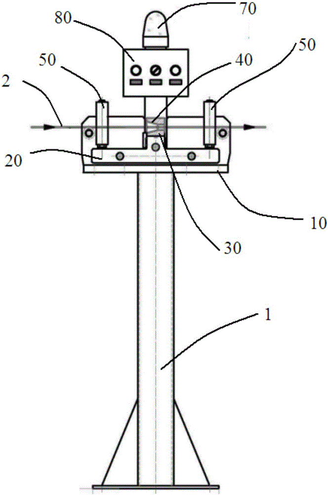
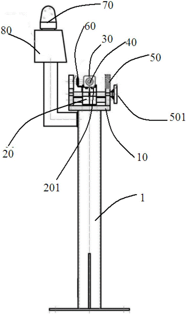
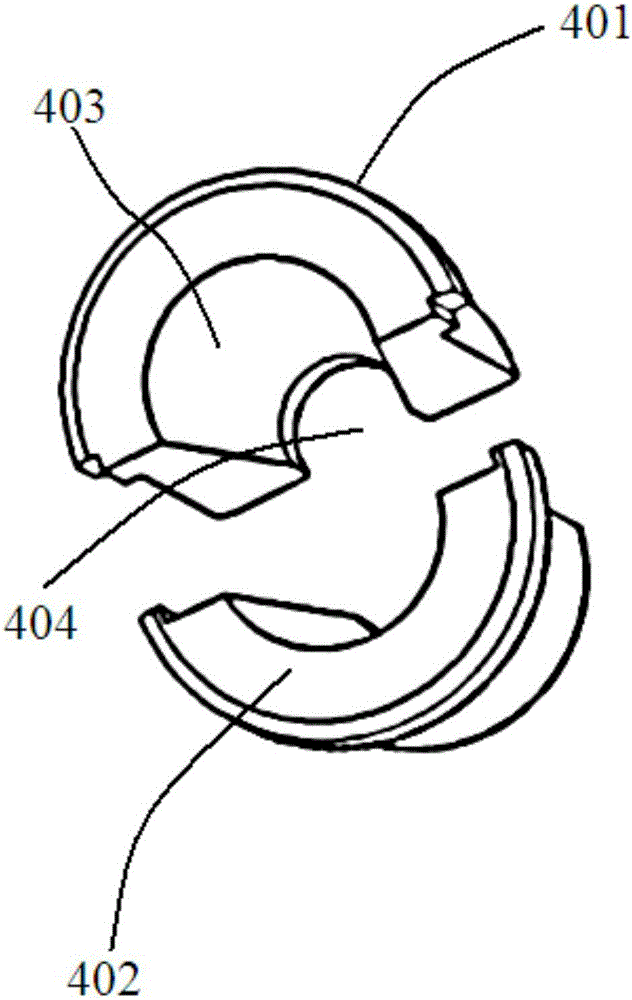
[0031] refer to Figure 1-2 As shown, a sheath wire bulge detection device is disclosed in this embodiment, and its supporting structure is a vertical frame 1. The top surface of the frame 1 is a detection workbench 10, on which a There is a base 20, a groove is provided on the end surface of the base 20, a magnet 201 is embedded in the groove, a mold base 30 is arranged on the top surface of the base 20, the magnet 201 absorbs the mold base 30, The two sides of above-mentioned mold base 30 are respectively provided with a group of guide rods 50, and cable 2 is inputted through two groups of above-mentioned guide rods 50 by wire-passing wheel, and two groups of above-mentioned guide rods 50 clamp cables; above-mentioned guide rods 50 can effectively prevent protection Set of jitter. It also effectively prevents the mold from entering the tractor and causing the tractor to fail when it does not fall off in time.

[0032] In this embodiment, the above-mentioned base 20 is an i...


PUM


Abstract

The invention discloses a sheathed line swelling detecting device which comprises a die base. A half die is placed in the die base. A magnet is placed below the die and attracts the die. The inner diameter of the die is slightly larger than the outer diameter of an optical cable sheath. Guide rods are designed on the two sides of the die base to stabilize an optical cable and prevent the optical cable from shaking. In normal production, the optical cable can smoothly pass through the half die, once the surface of the sheath swells, friction force can drive the half die out of the die base, at the moment, a proximity switch is switched on and an alarm is given, an operator is likely to process the swelling defect in time, record the quality and conduct rectifying and reforming by counting and analyzing the defect conditions, less rejected products are produced and unexpectedly flow to customers, the device is simple, practical, efficient and economical, and expected aims can be achieved.

Description

technical field [0001] The invention relates to the technical field of on-line optical cable production, in particular to a sheath wire bulge detection device and a detection method thereof. Background technique [0002] With the improvement of the market demand for optical cable products, more and more enterprises have increased the production speed of optical cables, which has become the main means for various enterprises to improve their market competitiveness. However, the continuous improvement of production speed has caused the problem of unstable sheath quality, and the sheath is prone to defects, such as bulges, concave ponds, uneven thickness, etc. Other defects can be found through inspection, and bulge defects currently rely on operators in China. Eyes and hands are used to identify, and the production line speed is very fast (generally more than 60 m / min), which is almost out of control. As a result, the product may be unqualified and scrapped, or even the unqual...

Claims


Application Information

Patent Timeline
IPC IPC(8): G02B6/44G01B5/08G01B5/28
CPCG01B5/08G01B5/28G02B6/4479
Inventor 陈钢孙庆杨城陆永尧陈澍
Owner JIANGSU ETERN
Learn More