

Reinforcement structure between front wheel casing and longitudinal beam and vehicle body adopting same
A technology for strengthening the structure and front wheel cover, applied to the upper structure, upper structure sub-assembly, vehicle parts, etc., can solve the problems of front wheel cover increase, cracking effect, insufficient torsional rigidity, etc., to achieve improved torsional rigidity and High stability, high torsional rigidity and stability, and reduced processing costs
- Summary
- Abstract
- Description
- Claims
- Application Information
AI Technical Summary
Problems solved by technology
Method used
Image

Examples
Embodiment 1
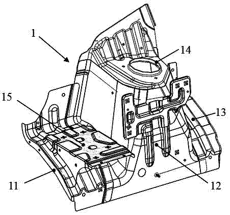
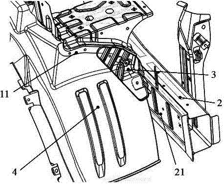
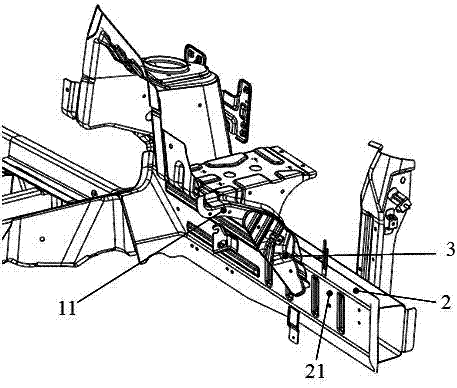
[0031] see Figure 1 to Figure 5 , the embodiment of the present invention provides a reinforcement structure between the front wheel house and the longitudinal beam of the automobile, including the front wheel house assembly and the longitudinal beam, the front wheel house assembly 1 includes the front wheel house body 12, connected to the The front wheel house front plate 11 and the front wheel house rear plate 13 on both sides of the front wheel house body 12 and the front suspension support plate 14 installed on the upper end of the front wheel house body 12, the longitudinal beam 2 has a longitudinal beam sealing plate 21 The front wheel house front panel 11 includes a main board 111 and a side board 112, the side of the main board 111 facing the outside of the vehicle body is the front side 1111, the side board 112 is fixedly connected with the longitudinal beam sealing board 21, the The reinforcement structure also includes a support reinforcement board 3, the support r...
PUM
 Abstract
Description
Claims
Application Information