Capacity configuration and cost allocation method for combined energy storage system of multi-main-body micro-grid group

A technology of microgrid group and cost sharing, which is applied to circuit devices, information technology support systems, and power generation forecasting in AC networks, etc., can solve the problem of difficulty in reasonably sharing the cost of energy storage systems, and achieve reasonable cost sharing of energy storage systems. , the effect of quantifying the degree of capacity demand

Active Publication Date: 2021-10-29
ECONOMIC & TECH RES INST OF HUBEI ELECTRIC POWER COMPANY SGCC
View PDF8 Cites 0 Cited by
  • Summary
  • Abstract
  • Description
  • Claims
  • Application Information

AI Technical Summary

Problems solved by technology

[0006] The purpose of the present invention is to overcome the defect and problem that the energy storage configuration method in the prior art does not take into account the difference in the capacity requirements of the multi-agent micro-grid for the joint energy storage system, resulting in the difficulty of reasonably apportioning the cost of the energy storage system, and to provide an energy storage system. Effective quantification of the multi-agent micro-grid's capacity requirements for the joint energy storage system and the reasonable allocation of the cost of the energy storage system for the multi-agent micro-grid group joint energy storage system capacity allocation and cost allocation

Method used


Image

  • Capacity configuration and cost allocation method for combined energy storage system of multi-main-body micro-grid group
  • Capacity configuration and cost allocation method for combined energy storage system of multi-main-body micro-grid group
  • Capacity configuration and cost allocation method for combined energy storage system of multi-main-body micro-grid group

Examples


Embodiment

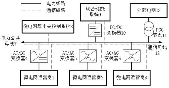
[0177] see figure 1 , the microgrid group is composed of different microgrid operators 1 to 3, among which, microgrid operator 1 is connected to the electric common bus 7 through AC / DC converter 4; microgrid operator 2 and microgrid operator 3 are respectively connected through The AC / AC converter 5 and the AC / AC converter 6 are connected to the electric common bus 7; the constructed combined energy storage system 9 is connected to the electric common bus 7 through the DC / DC converter 10; the electric common bus 7 passes through the PCC node 11 It is interconnected with the external power grid 13; the microgrid operators 1-3, the joint energy storage system 9 and the central control system 8 of the microgrid group communicate through the communication bus 12, and the central control system 8 of the microgrid group is responsible for unified operation and scheduling.

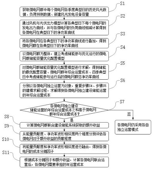
[0178] see figure 2 , a multi-agent microgrid group joint energy storage system capacity configuration and c...


PUM


Abstract

The invention discloses a capacity configuration and cost allocation method for a combined energy storage system of a multi-main-body micro-grid group, and the method comprises the following steps: taking a micro-grid group as a whole; establishing an energy storage capacity optimal configuration model to solve the optimal configuration capacity of energy storage, the annual comprehensive operation cost of the microgrid group, and the total net power curve of the microgrid group after considering the participation of the energy storage in operation in typical days of four seasons; taking independent operation of each micro-grid as an object, modeling and solving annual comprehensive operation cost of independent energy storage operation construction of each micro-grid, and calculating extra income obtained by joint energy storage system construction of the micro-grid group; and respectively evaluating the contribution degree of each micro-grid to the extra income from two dimensions of energy contribution degree and net power waveform similarity, thereby obtaining the cost allocation factor of each micro-grid, and calculating the annual operation cost needing to be undertaken after the joint operation of each micro-grid. According to the design, the capacity demand degree of the multi-main-body micro-grid for the combined energy storage system can be effectively quantified, and the cost of the energy storage system is reasonably shared.

Description

technical field [0001] The invention relates to the field of optimal configuration of power system microgrids, in particular to a method for capacity configuration and cost allocation of a multi-agent microgrid group joint energy storage system. Background technique [0002] In order to achieve the long-term dual-carbon goal of "30·60", it is necessary to build a clean, low-carbon, safe and efficient energy system, deepen the reform of the power system, and build a new power system with new energy as the main body. With the rapid development of distributed clean energy, electric vehicles, and user-side energy storage, the new power system undertakes the core functions of connecting multiple energy sources and supplying energy consumption to users, while supporting multiple user interactions and distributed renewable energy access. The microgrid will become an important part of the end of the new power system. [0003] The grid-connected microgrid can achieve stable operatio...

Claims


Application Information

Patent Timeline
Patent Type & Authority Applications(China)
IPC IPC(8): G06Q10/06G06Q50/06H02J3/00H02J3/28H02J3/46
CPCG06Q10/06312G06Q10/06315G06Q50/06H02J3/003H02J3/004H02J3/0075H02J3/28H02J3/381H02J3/466H02J2203/10H02J2203/20H02J2300/22H02J2300/28H02J2300/40Y02E70/30Y04S10/50
Inventor 汪致洵方仍存詹智红杨东俊刘畅侯婷婷贺兰菲
Owner ECONOMIC & TECH RES INST OF HUBEI ELECTRIC POWER COMPANY SGCC
Why Eureka
Try Eureka