Broadband VIV energy collecting device based on variable mass and efficiency verification method thereof
A technology of energy collection and quality change, which is applied in electromechanical devices, mechanical energy control, electrical components, etc., can solve the problems of lack of effective verification methods for energy collection, difficult quantitative evaluation of energy collection efficiency of devices, and low energy collection efficiency. The energy effect and collection efficiency are continuously stable, the power generation effect is increased, and the structural design is reasonable and simple.
- Summary
- Abstract
- Description
- Claims
- Application Information
AI Technical Summary
Problems solved by technology
Method used
Image

Examples
specific Embodiment approach 1
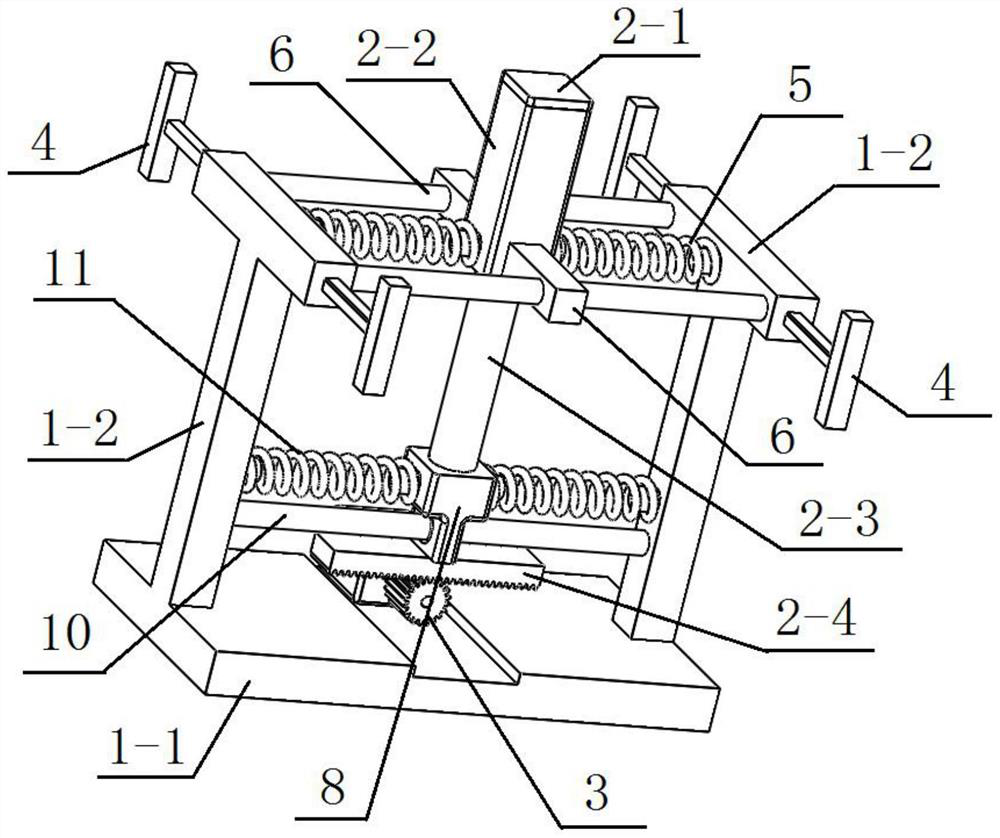
[0033] Specific implementation mode one: as Figure 1 to Figure 12 As shown, this specific embodiment adopts the following technical solutions: this embodiment includes a stand 1, an electromagnetic variable mass device 2, an electromagnetic generating mechanism 3, a plurality of galloping mechanisms 4 and a plurality of upper elastic members 5, and the stand 1 It is a 匚-shaped frame; the electromagnetic variable mass device 2 includes a cover 2-1, an upper cylinder 2-2, a longitudinal connecting column 2-3 and a moving bar 2-4, and the longitudinal connecting column 2-3 is vertically arranged on the stand Above 1, a plurality of galloping mechanisms 4 are arranged on both sides of the platform 1, an upper cylinder 2-2 is coaxially arranged on the top of the longitudinal connecting column 2-3, and the top of the upper cylinder 2-2 is detachably connected with a Covering 2-1, several electromagnetic coils 7 are arranged in the upper cylinder 2-2, an inner cavity is formed betwe...
specific Embodiment approach 2
[0036] Specific embodiment 2: This embodiment is a further limitation of specific implementation 1. The platform 1 includes a base 1-1 and two T-shaped columns 1-2, the base 1-1 is horizontally arranged, and the two T-shaped columns 1-2 2 vertically arranged side by side at both ends of the base 1-1; the longitudinal connecting column 2-3 is located between two T-shaped columns 1-2, and the bottom end of each T-shaped column 1-2 is fixedly connected with the base 1-1 , each T-shaped column 1-2 top ends are respectively provided with a galloping mechanism 4 .
specific Embodiment approach 3
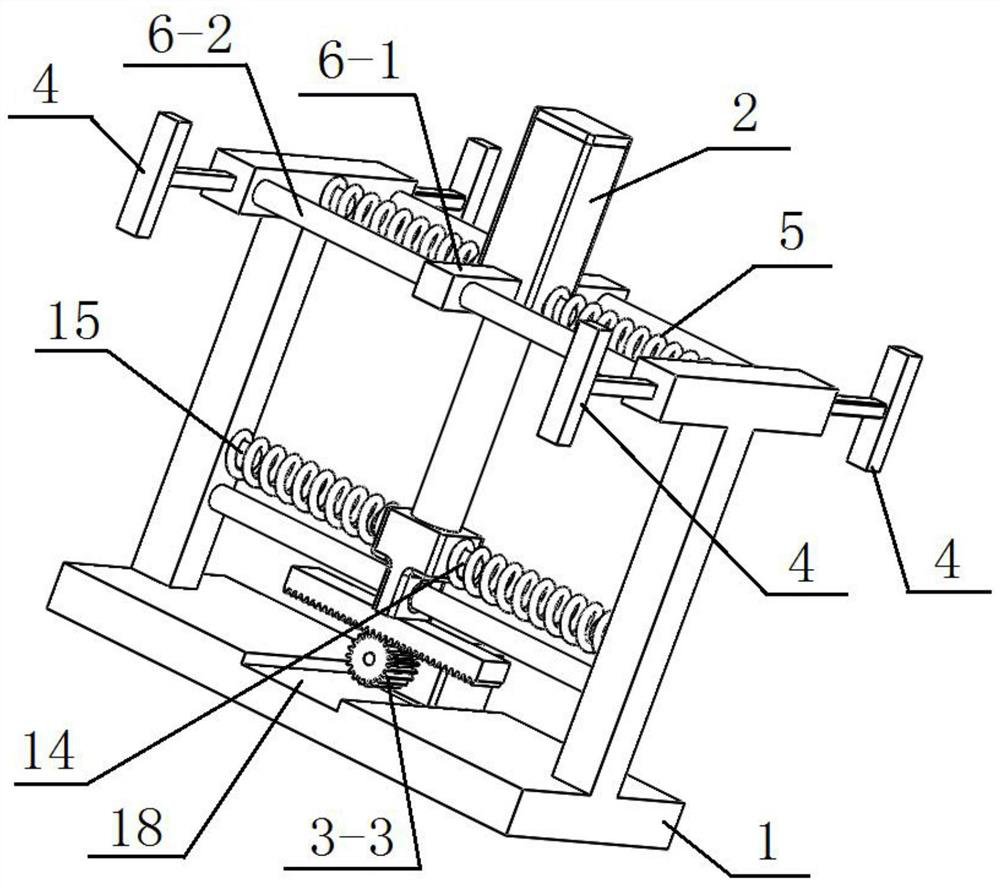
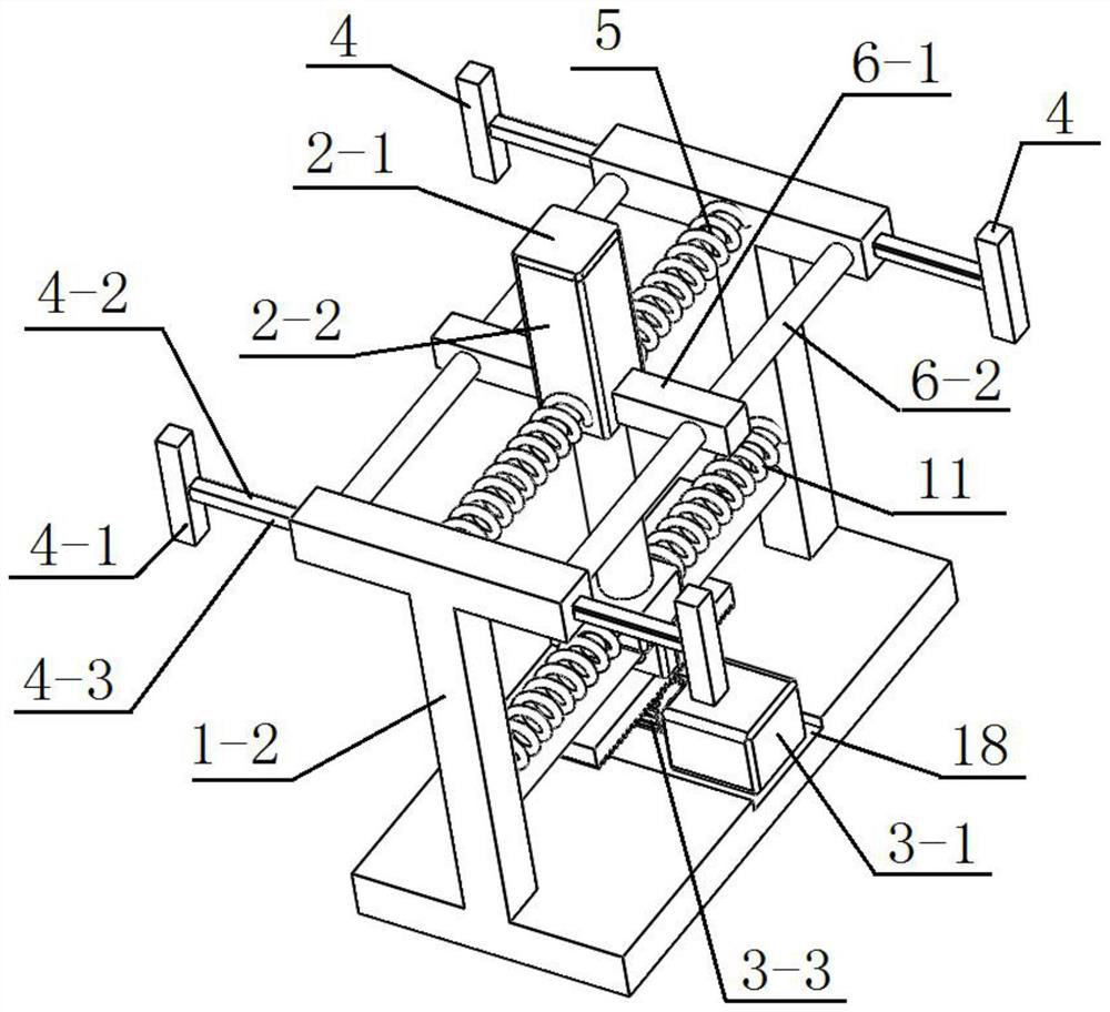
[0037] Specific Embodiment 3: This embodiment is a further limitation of specific implementation 1 or 2. The upper cylinder body 2-2 is equipped with two connecting pieces 6, and the upper cylinder body 2-2 is arranged between the two connecting pieces 6. Each A connecting piece 6 includes a connecting block 6-1 and a first beam 6-2, one end of the connecting block 6-1 is fixedly connected to the outer wall of the upper cylinder 2-2, and the other end of the connecting block 6-1 is processed with a first Through hole 19, one end of the first light column 6-2 is fixedly connected to one of the T-shaped columns 1-2 in the two T-shaped columns 1-2, and the other end of the first light column 6-2 passes through the first through hole 19 is fixedly connected with the other T-shaped column 1-2 of the two T-shaped columns 1-2, and the upper cylinder 2-2 reciprocates along the length direction of the first optical column 6-2 through the connecting block 6-1.
PUM
 Abstract
Description
Claims
Application Information
 - R&D
- Intellectual Property
- Life Sciences
- Materials
- Tech Scout
- Unparalleled Data Quality
- Higher Quality Content
- 60% Fewer Hallucinations
Browse by: Latest US Patents, China's latest patents, Technical Efficacy Thesaurus, Application Domain, Technology Topic, Popular Technical Reports.
© 2025 PatSnap. All rights reserved.Legal|Privacy policy|Modern Slavery Act Transparency Statement|Sitemap|About US| Contact US: help@patsnap.com