VR intelligent equipment capable of improving comfort
A smart device and comfort technology, applied in the field of VR smart devices, can solve problems such as impact, and achieve the effects of improving comfort, improving heat dissipation, and enhancing realism
- Summary
- Abstract
- Description
- Claims
- Application Information
AI Technical Summary
Problems solved by technology
Method used
Image

Examples
Embodiment 1
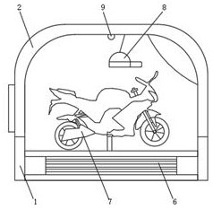
[0034] Such as figure 1 , 2 , 3, 5, and 6, a VR smart device that improves comfort, includes a chassis 1, a power unit 6, a VR motorcycle body 7 and VR glasses 8, and the chassis 1 is provided with a power unit 6 , and the upper end of the power unit 6 is provided with a VR motorcycle body 7 and VR glasses 8, and the speed adjustment mechanism of the VR motorcycle body 7 is connected with the VR glasses 8;
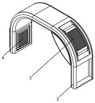
[0035]The upper end of chassis 1 is provided with auxiliary type support 2, and auxiliary type support 2 comprises support frame 201, cavity 202, first installation groove 203, seal cover 204, through hole 205 and second installation groove 208, the support frame 201 The outer wall is provided with a cavity 202, and the front end arc portion of the support frame 201 is provided with a first installation groove 203, and a fan adjustment structure 3 is installed in the groove of the first installation groove 203, and a sealing cover is provided at the mouth of the cavity 20...
Embodiment 2
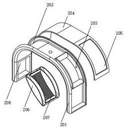
[0038] Such as figure 2 , 4 As shown in , 6, 7, and 8, a fan adjustment structure of a VR smart device that improves comfort, the fan adjustment structure 3 includes a side piece 301, a drive shaft connecting pipe 302, a rotating frame 303, a storage bin 304, and an arc-shaped support bar 305, the fan 306, the first arc-shaped filter screen 307 and the second arc-shaped filter screen 308, and the groove inner wall of the first installation groove 203 is provided with a side piece 301, and the middle of the end face of the side piece 301 is provided with a drive shaft connecting pipe 302 , and the drive shaft connection pipe 302 runs through the first installation groove 203 and is inserted into the cavity 202. The first drive motor in the cavity 202 is connected to one of the drive shaft connection pipes 302, and the two side pieces 301 are connected with Rotating frame 303, and the arc surface of rotating frame 303 is provided with placing bin 304, is provided with arc supp...
Embodiment 3
[0040] Such as image 3 As shown, another auxiliary bracket for a VR smart device that improves comfort, the auxiliary bracket 2 also includes an auxiliary bracket 206 and a first guide vane 207, and the arc portion on the front side of the inner wall of the bracket 201 is provided with Two auxiliary frames 206, the two auxiliary frames 206 are provided with a first guide vane 207, and the auxiliary frame 206 is fixedly connected with the support frame 201, the first guide vane 207 is facing the first installation groove 203, the first guide vane The flow vane 207 is movably connected with the auxiliary frame 206, and the first guide vane 207 faces the driver's seat of the VR motorcycle body 7, the auxiliary frame 206 is installed at the fan adjustment structure 3, and the auxiliary frame 206 and the first guide vane 207 Covering the fan adjustment structure 3, the first guide vane 207 can realize the adjustment of the wind direction, and further ensure that the wind direction...
PUM
 Abstract
Description
Claims
Application Information
PatSnap Eureka turns technology decisions into work you can execute. Powered by our Innovation Knowledge Graph, it runs expert workflows across engineering, life sciences, materials and intellectual property. Get your review-ready output in minutes.


