Supercharge Your Innovation With Domain-Expert AI Agents!

Electrical automation equipment

A technology of electrical automation and equipment, applied in the direction of thin material processing, conveying filamentous materials, transportation and packaging, etc., can solve the problems of damaging the quality and safety of cables, affecting the progress of conveying work, and prone to wear and tear, etc., to achieve Achieve protection, promote adsorption, and improve stability

Active Publication Date: 2021-11-02
STATE GRID SICHUAN ELECTRIC POWER
View PDF7 Cites 0 Cited by
  • Summary
  • Abstract
  • Description
  • Claims
  • Application Information

AI Technical Summary

Problems solved by technology

[0006] Aiming at the deficiencies of the prior art, the present invention provides an electrical automation equipment, which solves the problem that the existing electrical automation equipment is prone to position deviation due to the weight and motion inertia of the electrical cable itself and falls off from the equipment during the use of the existing electrical automation equipment. , it is easy to affect the work progress of the transportation, and at the same time, it is easy to wear and tear itself, which will damage the quality and safety of the cable.

Method used


Image

  • Electrical automation equipment
  • Electrical automation equipment
  • Electrical automation equipment

Examples


Embodiment 1

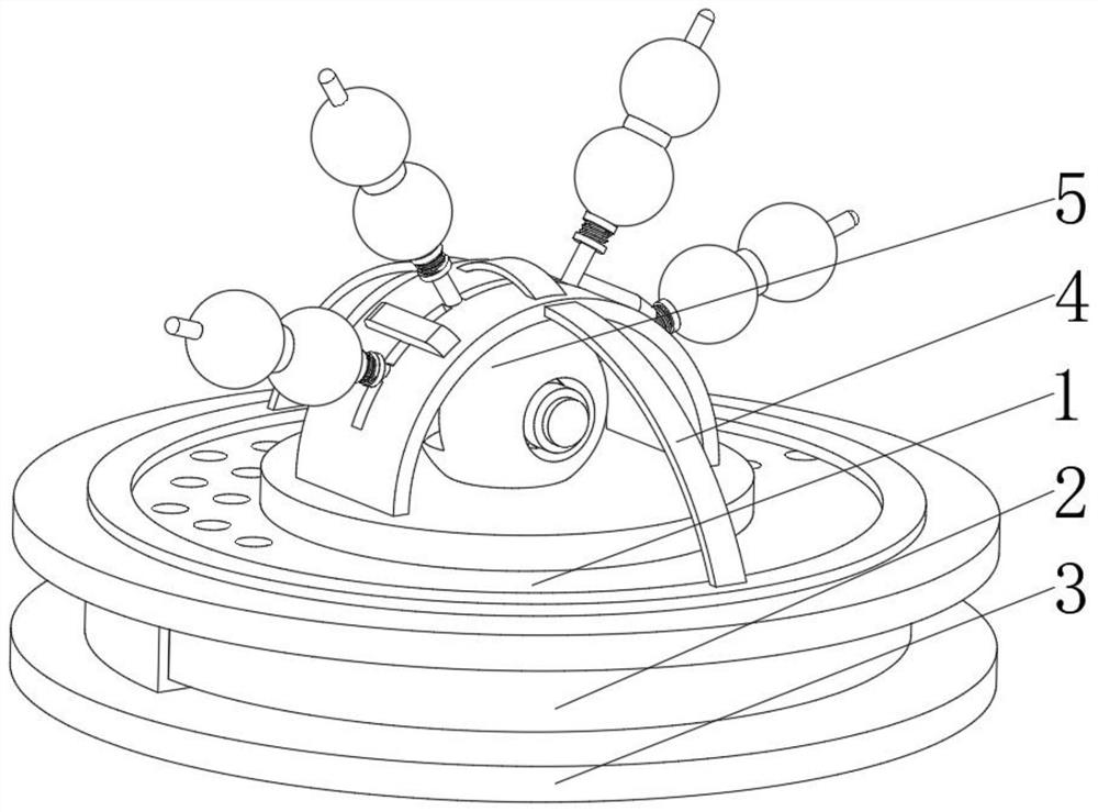
[0037] see Figure 1-3 , the present invention provides a technical solution: an electrical automation equipment, specifically comprising:

[0038] Orbit ring 1, the orbit ring 1 has a ring-shaped rail, and a collection and cleaning mechanism 2 installed at the bottom of the ring-shaped rail, and a base plate 3 fixed at the bottom of the collection and cleaning mechanism 2, and a support frame rod arranged at the top of the ring-shaped rail 4. Through the annular design of the track ring 1 itself, it is convenient to adjust the angle of the components, and there is no need to move and adjust the position after it is installed by itself, which is suitable for the needs of various working environments.

[0039] Lead mechanism 5, this lead mechanism 5 has an antenna body, and the antenna body is installed on the top of the gathering cleaning mechanism 2, and the lead mechanism 5 includes:

[0040]Shaft fixing mechanism 51, the shaft fixing mechanism 51 has a spherical body, and ...

Embodiment 2

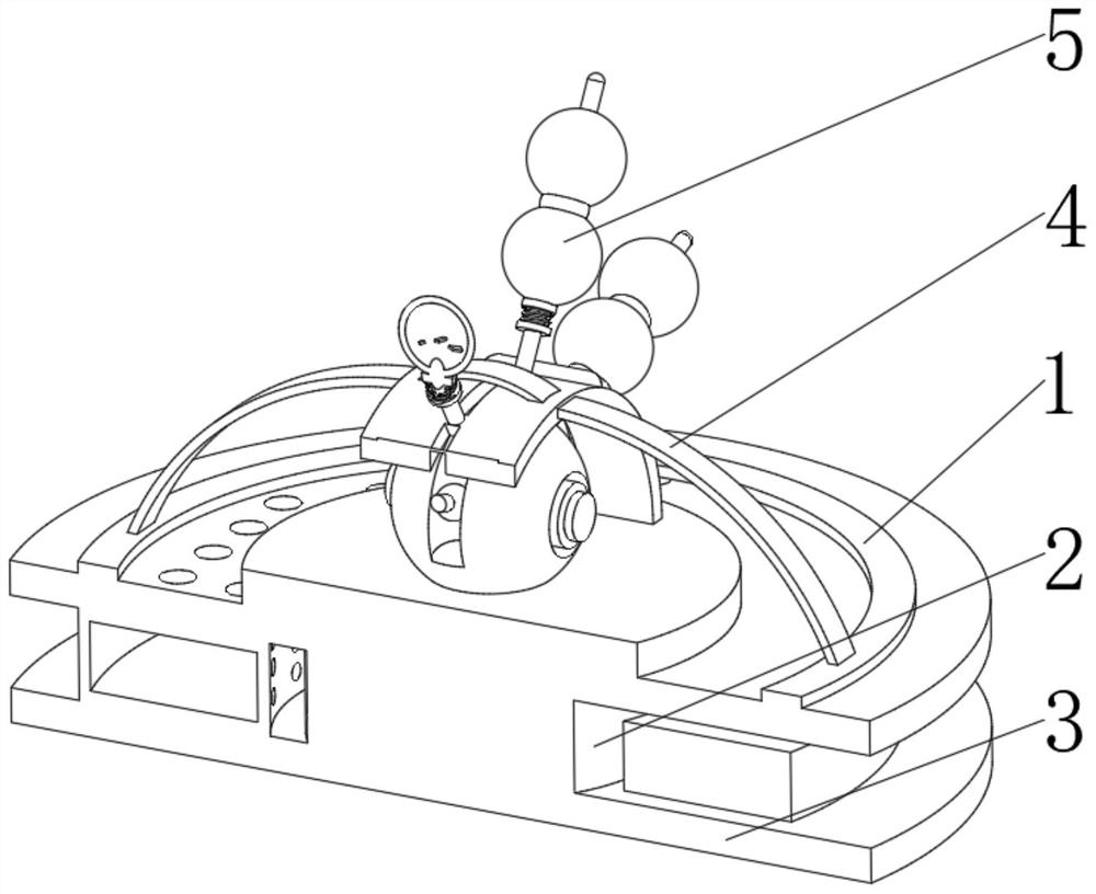
[0044] see Figure 1-4 , on the basis of Embodiment 1, the present invention provides a technical solution: the collection and cleaning mechanism 2 includes an air suction pump 21, and a support plate 22 installed on the top of the air suction pump 21, and the opening on the top side of the support plate 22 The collection hole 23, the filter screen ring 24 installed at the bottom of the support plate 22 and below the collection hole 23, and the cleaning ring rod 25 installed in the inner cavity of the filter screen ring 24. The collection hole 23 is set at the front end of the conveying, and at the same time, the auxiliary airflow is used for suction to remove the dust or magazines left by the cable on the receiver, maintain the friction between the component itself and the cable, and realize the positioning protection of the cable position .

[0045] The filter ring 24 and the cleaning ring rod 25 are located above the base plate 3 , and the bottom of the collecting hole 23 ...

Embodiment 3

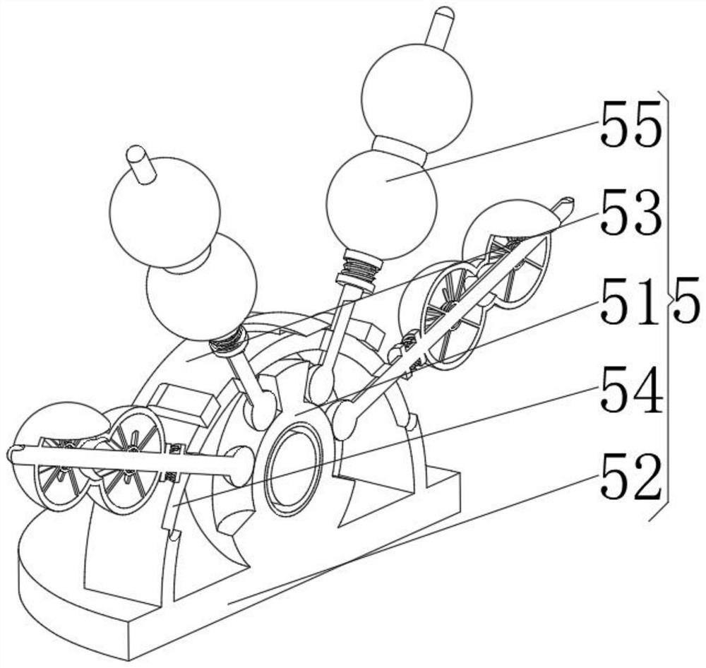
[0048] see Figure 1-6 , on the basis of Embodiment 1 and Embodiment 2, the present invention provides a technical solution: the fixed axis mechanism 51 includes a ball seat 511, and a mounting hole 512 opened in the middle of the ball seat 511, and opened outside the ball seat 511 The limiting grooves 513 on both sides of the surface, the mounting balls 514 installed inside the limiting grooves 513 , and the protective sleeve 515 arranged in the inner cavity of the mounting hole 512 . Through the spherical design of the ball seat 511, it is convenient to disperse the impact force on the surface and realize the protection of the whole mechanism. At the same time, the installation equipment of the protective sleeve 515 is convenient for counterweight, which can be changed according to the intensity of transportation, and the overall stability of the mechanism is improved.

[0049] The outer surface of the installation ball 514 is connected to the winding mechanism 55 , and the ...


PUM


Abstract

The invention discloses electrical automation equipment. The electrical automation equipment specifically comprises a wire guiding mechanism, the wire guiding mechanism is provided with an antenna body, and the antenna body is arranged at the top of a gathering and cleaning mechanism; and the wire guiding mechanism comprises a fixed shaft mechanism, and the fixed shaft mechanism is provided with a spherical body, a mounting plate fixed at the bottom of the spherical body, a limiting ring plate mounted at the top of the mounting plate and located on the outer side of the spherical body, a rail through hole formed in the middle position of the top of the limiting ring plate and wire winding mechanisms arranged in an inner cavity of the rail through hole in the limiting ring plate. The invention relates to the technical field of electrical automation. Through the design of surface coils and inner iron cores of electromagnetic V rods, magnetic induction lines generated when magnetic contact balls rotate are cut, the electromagnetic V rods generate electromagnetic force to get close to each other, planar shape changing is conducted on ear-shaped balloons, the ear-shaped balloons are attached to adjacent components, and a conveyed cable is surrounded to prevent falling or position changing.

Description

technical field [0001] The invention relates to the technical field of electrical automation, in particular to electrical automation equipment. Background technique [0002] With the development of economy and society, various electrical automation production equipment has been more and more used in production. When all kinds of electrical automation production equipment are used in production, generally no manual operation is required or less manual operation is required to achieve the purpose of reducing labor costs. [0003] According to Chinese patent CN108163636A, the frame; the frame is provided with a bearing frame for carrying the cable roll; a guide that is connected to the frame and can guide the horizontal movement of the cable released by the cable roll guiding device; and a tensioning mechanism arranged between the bearing frame and the guiding device and connected to the frame; wherein, the tensioning mechanism includes: a tensioning wheel connected in rotatio...

Claims


Application Information

Patent Timeline
IPC IPC(8): B65H57/14
CPCB65H57/14
Inventor 郭海燕
Owner STATE GRID SICHUAN ELECTRIC POWER
Features
  • R&D
  • Intellectual Property
  • Life Sciences
  • Materials
  • Tech Scout
  • Unparalleled Data Quality
  • Higher Quality Content
  • 60% Fewer Hallucinations
Learn More