Automatic detection system for pressing of lifting sleeve

An automatic inspection and casing technology, which is applied in the direction of inflation gas pressure measurement, fluid pressure measurement, measuring device, etc., can solve the problems of lifting casing explosion, lifting casing lifting action can not be carried out smoothly, inflation pressure instability, etc. To achieve the effect of improving safety

Pending Publication Date: 2021-11-02
QINGDAO ZEHAO AUTO PARTS
0 Cites 0 Cited by

AI-Extracted Technical Summary

Problems solved by technology

[0004] This method of inflating the lifting sleeve has the following problems: the inflation pressure after inflating the lifting sleeve is unstable. If the inflation pressure is too low,...

Method used

The concrete structure of clamp 7 is as follows: clamp 7 comprises clamp main body, and the manufacturing material of clamp main body is metal, specifically can be stainless steel, and clamp main body adopts integrated structure, can improve the structure of clamp main body like this Strength, improve its service life. On the main body of the clamp, there is a clamp hole opposite to the front card slot and used for inserting the top end of the cylinder sleeve of the lifting sleeve a. The clamp hole is a round hole structure, a...

Abstract

The invention discloses a lifting sleeve pressing automatic inspection system. The system comprises a support, an air inflation assembly and a pressing detection assembly, wherein the support is used for bearing a lifting sleeve, the air inflation assembly comprises an air inflation assembly installation block, the air inflation assembly installation block can linearly reciprocate towards a rear supporting plate, an air inflation head opposite to a rear clamping groove is arranged on the air inflation assembly installation block, the pressing detection assembly comprises a detection assembly installation block, the detection assembly installation block can do reciprocating motion towards the front supporting plate along a straight line, a force sensor is fixedly arranged on the detection assembly installation block, a clamp is arranged on the force sensor, the clamp and the front clamping groove are oppositely arranged, and the clamp is used for clamping an air cylinder sleeve of the lifting sleeve to do linear reciprocating motion. According to the system, whether inflation and pressing of the lifting sleeve are qualified or not can be synchronously detected on line while inflation and pressing of the lifting sleeve are achieved, and safety of lifting sleeve products is improved to a great extent.

Application Domain

Inflated body pressure measurement

Technology Topic

Structural engineeringReciprocating motion +2

Image

  • Automatic detection system for pressing of lifting sleeve

Examples

  • Experimental program(1)

Example Embodiment

[0027] The present invention will be described in detail below with reference to the accompanying drawings. Various examples of the present invention is provided by way of explanation and not limitation of the present invention embodiment. Indeed, those skilled in the art will appreciate, may be made modifications and variations in the present invention without departing from the scope or spirit of the invention. For example, features illustrated or described as part of one embodiment may be used with another embodiment to yield yet another embodiment. Accordingly, it is desirable that the present invention encompasses the appended claims and their equivalents fall such modifications and variations within the scope of the.
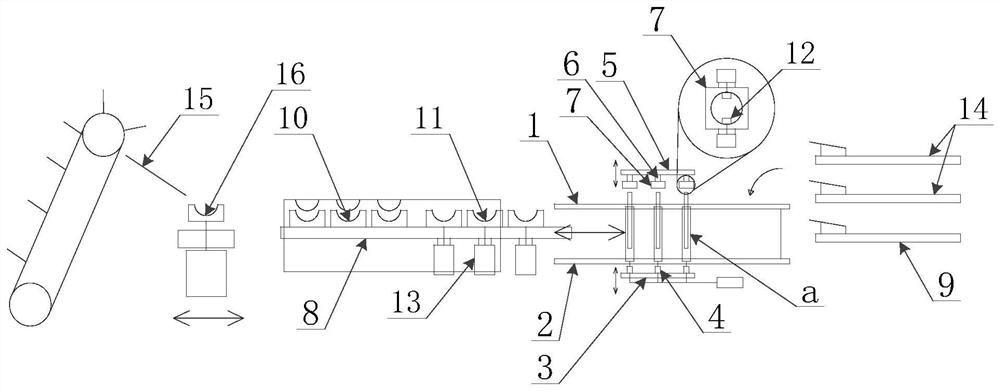
[0028] In the description of the present invention, the term "longitudinal", "lateral", "upper", "lower", "front", "rear", "left", "right", "vertical", "horizontal", " orientation or positional relationship top, "" bottom, "etc., indicate the position or orientation is based on the relationship shown in the drawings, are merely for convenience of description the present invention is not a requirement of the present invention must be in a particular orientation and configuration operations, therefore not to be limit the present invention. Used in the present invention, the term "coupled", "connected" are to be broadly understood, for example, may be a fixed connection, or may be detachably connected; may be directly connected, can also be connected indirectly through an intermediate member, the ordinary skilled the skilled person will be appreciated that the specific meanings depending on the circumstances.
[0029] Please refer to figure 1 , figure 1 A schematic diagram of the structure of the lifting sleeve suppress automatic inspection system embodiment of the present invention.
[0030] The present invention provides an automatic inspection system lifting pressure sleeve, the pressure sleeve automatic lifting inspection system includes the following components.
[0031] A first portion for supporting a cannula lift bracket
[0032] Lifting the sleeve to a cylindrical structure, and to suppress during detection, a lift sleeve are arranged transversely along a straight line, it is arranged laterally above means: when a lifting sleeve arranged in a vertical lift axis of the sleeve to its transport direction .
[0033]The stent is a member for supporting the lifting sleeve A in the pressing and detection, specifically, the stent includes a front plate 1 and the rear sheet 2, the front plate 1, and the rear sheet 2 are disposed at an elevation On both sides in the sleeve A transport direction, the front branch plate 1 is used to support the front end of the lifting sleeve A (the lift sleeve A is provided at one end of the cylinder sleeve), and the rear branch plate 2 is used to the lifting sleeve A The rear end (the outer sleeve of the lifting sleeve A is provided with one end of the inflatable one-way valve, and one end of the outer sleeve can be actively provided with an air cylinder sleeve, and the other end of the outer sleeve is provided with an inflatable one-way valve).
[0034] In the lifting sleeve A structure, the cylinder sleeve is a cylindrical structure, and the outer sleeve is a cylindrical structure. In order to be able to stabilize the lifting tube A, the present invention is defined: the front branch plate 1 is a plate structure provided with a vertically disposed, and a front card slot is provided on the upper edge of the front plate 1, the front card slot is the curved groove, and then The branch plate 2 is a vertically disposed plate structure, and the upper edge of the rear branch 2 is provided with a rear card slot, the rear card slot is the curved groove, and the front card slot is opposed to the axial direction of the lifting sleeve A. Set and form a card slot unit for causing a lifting sleeve A, the lifting sleeve A card can be stably engaged in the card slot unit.
[0035] Specifically, the front branch 1 and the rear sheet 2 are the metal plate, preferably a stainless steel sheet, and of course the aluminum profile plate can also be applied to the present invention.
[0036] The front branch plate 1 is disposed vertically with the rear branch plate 2, and the front branch plate 1 is disposed parallel to the rear branch plate 2, and the front branch plate 1 is disposed between the rear bracket 2, the front plate 1 and the side surface opposite the rear bracket 2 are Inside, the other side is the outer side.
[0037] Part 2, inflatable components
[0038] The present invention is provided with an inflatable assembly in the outer side of the rear branch 2, and the inflatable assembly is a device for charging nitrogen on the lifting sleeve A in the present invention.
[0039] Specifically, the inflatable assembly includes an inflatable assembly mounting block 3, and the inflator mounting block 3 can be moved toward the rear branch plate 2 along the straight line, and a pneumatic head 4 opposite the rear card slot is provided on the air assembly mounting block 3. The inflatable assembly also includes a nitrogen source, and the nitrogen source is coupled to the inflatable head 4 through a pipeline system (composed of high pressure tube and solenoid valve), by controlling the opening and closing of the solenoid valve, the inflation of the lifting sleeve A can be realized. The pneumatic head 4 is disposed on the pneumatic assembly mounting block 3 and can be linked with the pneumatic assembly mounting block 3, the inflatable head 4 can be against the inflatable one-way valve at the end of the lifting sleeve A, and the inflatable unidirectional valve is opened after the air (lifting sleeve The A card is fitted onto the front plate 1 and the rear sheet 2 so that the air head 4 can open the inflatable single-way valve), and can be charged to the lifting sleeve A into nitrogen.
[0040] Part III, pressing the detection component
[0041] The pressing detection assembly disposed outside the front plate 1 is used to detect the pressing pressure of the lift tube A.
[0042] Specifically, the pressing detecting assembly includes a detection component mounting block 5, and the detecting component mounting block 5 is disposed outside the front plate 1, and the detection component mounting block 5 can move forward toward the forward plate 1 along the straight line, in the detection component mounting block. 5 Mounting the power sensor 6, the force sensor 6 is disposed on one side of the detection component mounting block 5 toward the front plate 1, and fixedly disposed on the force sensor 6, the clamp 7, the clamp 7 and the front card slot are disposed. The clamp 7 is used to sandwich the cylinder sleeve of the lifting sleeve A for linear reciprocating. The clamp 7 caught the cylinder sleeve outward, and is inflated from the pneumatic head 4 to the outer sleeve, and then the clamp 7 is pushing back to the cylinder sleeve back, and the filled nitrogen is compressed to apply one to the cylinder sleeve. The force, the force is the need to detect the inflation pressure, and the inflation pressure can be detected by force sensor 6. When the charged nitrogen is too large, the force value of the lift sleeve A feedback is large. When the filled nitrogen is less, the weight value of the lift sleeve A feedback is smaller, so that the force value obtained by the force sensor 6 can be It is determined whether the lifting sleeve A is inductive.
[0043] In order to achieve a plurality of lifting sleeve A simultaneous inflation, the present invention has a plurality of front card slots on the front branch plate 1, and a plurality of rear card slots are provided on the rear sheet 2, the front card slot is opposed to the rear card slot. Set and forming a card slot unit, the card slot unit in the present invention sets a plurality of pneumatic head 4 and a force sensor 6, and each force sensor 6 is set, each force sensor 6 is set. There is a clamp 7.
[0044] The specific structure of the clamp 7 is as follows: The clamp 7 includes a clamp body, a molded material of the clamp body, which may be a stainless steel, a clamp body employ a integrated structure, which can improve the structural strength of the clamp body, improve Its service life. The clamp hole inserted with respect to the front card slot is opened on the jaw body and used to lift the cylinder sleeve of the lifting sleeve A, the clamp hole is a circular hole structure, and the diameter of the clamp hole is greater than the top end of the cylinder sleeve. diameter. The block 12 is provided on the clamp body, and the block 12 is disposed in the clamp hole, and the block 12 can reciprocate in the axial ribbon direction perpendicular to the clamp hole, and the block 12 is lowered. The cylinder sleeve is accomplished on the cylinder sleeve to move the cylinder sleeve to carry out straight reciprocating motion.
[0045] Specifically, the air pressure cylinder is provided on the jaw body, and the block 12 is connected to the pressure cylinder shaft of the air pressure cylinder. Of course, the air pressure cylinder can be replaced with a hydraulic cylinder in the present invention.
[0046] Part 4, conveying components
[0047] The conveying assembly is an assembly that implements the lift tube A along the straight line in the present invention.
[0048] The conveying assembly includes a conveying slider disposed in the inner side of the stent (the front branch plate 1 provided by the spacing, the rear sheet 2, the front branch plate 1 and the rear bobbin 2 interval) transport slider, conveying slider in front plate 1 There may be in the direction of the conveying direction of the lift sleeve A in the conveying direction of the lifting sleeve A.
[0049] Specifically, the present invention is provided with a conveying slide, and the conveying slider can be linearly moveable on the conveying slide, and the present invention can also set a limit block on the conveying slider and located in the limit position of the transport slider movement. The motion of the conveying slider is limited. For the driving of the conveying slider, the present invention is preferred to use belt drives.
[0050] The conveying slider is mainly realized in reciprocating motion between the stent, the conveying of the lifting sleeve A is carried out in a stepper mode, and the specific forward operation of the lifting sleeve A is as follows: lifting sleeve A lifts, advancement, aligning the bracket The card slot unit is falling, thereby completing a step forward. For the lifting and falling of the lifting sleeve A, the present invention is fixed to the conveying slider (can be a cylinder or a hydraulic cylinder), which can be lifted on the conveying slider by the first lifting device. The lifting platform 8, the conveying litter 8 can be integrated by a polymer material, and the upper side surface of the conveying stage 8 is provided with a groove structure in which the outer side shape of the lifting sleeve A is provided, which is provided on the conveying liter 8. The conveying card slot of the lifting tube A is driven by the conveying and lowering stage 8 by the first lifting device (transporting the lifting platform 8 rises to lift the lifting sleeve A) or decreases (transporting the lifting platform 8) fall).
[0051] Further, the present invention is provided along the conveying direction of the rising sleeve A, and the collecting platform 9 is provided in front of the bracket, and the front end of the collection platform 9 is provided with a slide rail, the sliding tilt setting is used for dragging. The lifting sleeve A is rolled by the lifting sleeve A in the slide rail, and the conveying liter 8 drop down the lifting sleeve A falls along the rail to the collecting platform 9.
[0052] Based on the above-described structural design, the operation of the lifting sleeve A is as follows: the conveying slider is located in the initial position (at this time, the conveying layer 8 is at the lowest position state), and the lift tube A is placed in the conveying card slot of the conveying stage 8. On the upper, after the rendering tube A is completed, the conveying liter 8 is lifted to the highest position (lifting sleeve A is lifted), then transport the slider action and advancement, the conveying litter 8 drops to the lowest position, transport lifting When the stage 8 drops, the lifting sleeve A on the conveying platform 8 can be truck onto the bracket and disengaged from the transport litting stage 8, and the conveying layer 8 is reset to the initial position in the initial position in the lowest position. Place.
[0053] By extending the length of the conveying slider, the present invention can also output the lifting sleeve A of the completion of the air pressing operation.
[0054] Specifically, the fixed conveying tank 10 and the canonial sorting conveying card slot 11 are provided in the conveying lifting stage 8, and the fixed conveying card slot 10 is disposed in the rear of the sorting conveying card slot 11 along the conveying direction of the rising sleeve A. The second lifting device 13 is provided on the conveying litting stage 8, and the sorting conveying card groove 11 is disposed on the second lifting device 13 and the lifting operation is performed by the second lifting device 13, and the present invention also provides a controller, control. The controller is connected to the force sensor 6, and the controller is controlled to the second lifting device 13. The force sensor 6 detects the force value of the lifting sleeve A feedback, compared by the controller, when the force value is in the threshold, the lifting sleeve A is pressed normally, when the force value is outside the threshold, the lifting sleeve is abnormal. . The present invention can selectively output the lifting sleeve A according to the result of the determination result (whether or not the lift sleeve A is maintained normally). Further, a sorting carriage 14 is provided above the collecting platform 9 for detecting the output of unqualified lifting sleeve A. The output operation of the lifting sleeve A is as follows: When the lifting tube A is pressed normally, the lifting sleeve A is output by the conveying slider and the conveying litter 8, when the lifting sleeve A is abnormal, transport the lifting platform 8 With the sorting conveying card groove 11 to raise the lifting sleeve A of the pressing abnormality, output by the sorting carriage 14.
[0055] Specifically, a plurality of fixed delivery card grooves 10 and a plurality of sorting conveying card slots 11 are provided on the conveying liter 8, wherein the set number of fixed conveying card slots 10 is the same as the number of sets of space slot units, and the sorting is delivered. The number of sets of spacers 11 is the same as the number of sets of space slot cells.
[0056] Part 5, automatic feeding device
[0057] The automatic feeding device includes an addition slide 15, which can be provided with a feed lifting stage 16 on the feed slide 15, and is provided with a feed groove, a conveying slider, and a conveying slider, and a conveying slider, and The conveying litter 8 is both a frame structure, and the sliding slide 15 can slide to the conveying liter 8.
[0058] In the present invention, the structure of the automatic feeding device is approximated to the structure of the conveying assembly, which is transferred to a step of championing.
[0059] Section 6, marking components
[0060] The marking assembly is disposed on the collection platform 9, and the marking assembly includes a hydraulic device, a hydraulic device including a telescopic shaft, a shaft end of the telescopic shaft, is provided with a steel printing of the external surface of the lifting sleeve A, by hitting The labeled assembly can make a marking of the lifting sleeve A for the test.
[0061] In the above-described structural design, the present invention detects the lifting sleeve A after the inflation, the lifting sleeve A can be divided into three categories: qualified, low air pressure, high air pressure. The lifting sleeve A is divided into three kinds of gas pressures, high, low, and distributes a sorting platform for high gas pressure rope boat A. A sorting platform is assigned to low gas pressure lifting sleeve A. For qualified products, use collection Platform 9, and passed the collection platform 9 to enter a qualified lift sleeve A into the next step, such as a marking process.
[0062]The present invention provides a lifting sleeve pressing automatic inspection system, including a bracket, a gas assembly, and a pressure detection assembly, a bracket for carrying a rising sleeve A, a bracket including a front branch plate 1 and a rear sheet 2 having a spacer disposed. The front branch plate 1 is provided on the front branch 1, and the rear card slot is provided on the back bobbin 2, the front card slot and the rear card slot are configured and form a card slot unit for caught a lifting sleeve A, including the inflatable assembly including Inflatable component mounting block 3, the inflatable assembly mounting block 3 can be moved toward the rear sheet 2 along the straight line, and the inflatable head 4 opposite the rear card slot is provided on the inflatable assembly mounting block 3, the inflatable head 4 can be connected to the lifting sleeve The inflated unidirectional valve at the end of the tube A differs to the lifting sleeve A, the pressure detection assembly includes the detection component mounting block 5, and the detection component mounting block 5 can move forward toward the forward plate 1 along the straight line, in the detection component installation The force sensor 6 is fixed to the block 5, and the jaw 7 is provided on the force sensor 6, the clamp 7 is disposed with the front card slot, and the clamp 7 is used to sandwich the cylinder sleeve of the lifting tube A for linear reciprocating. The present invention is an automatic inflation and air pressure detection system capable of detecting whether or not the gas pressure in the core member (lifting sleeve A) of the lifting seater is qualified. Through the above-described structural design, the stent can stabilize the lifting sleeve A and then pneumatically by the pneumatic head 4, and the pressure detection assembly can drive the cylinder sleeve movement. When the cylinder sleeve is pushed, the detection of inflation pressure can be realized. . Accordingly, the present invention achieves that while improving the lifting sleeve A, it is also possible to synchronize online synchronous detection on whether the lifting sleeve A inflation is passed, greatly improves the safety of the lifting sleeve A product.
[0063] The above is only the preferred embodiments of the present invention, and is not intended to limit the invention, and the present invention can have various changes and variations for those skilled in the art. Any modification, equivalent replacement, improvement, etc. according to the present invention should be included within the scope of the invention.

PUM

no PUM

Description & Claims & Application Information

We can also present the details of the Description, Claims and Application information to help users get a comprehensive understanding of the technical details of the patent, such as background art, summary of invention, brief description of drawings, description of embodiments, and other original content. On the other hand, users can also determine the specific scope of protection of the technology through the list of claims; as well as understand the changes in the life cycle of the technology with the presentation of the patent timeline. Login to view more.

Similar technology patents

Trusted computing platform chip applicable to mobile communication equipment and authentication method thereof

InactiveCN101986641Aimprove securityachieve security
Owner:HANGZHOU SYNOCHIP DATA SECURITY TECH CO LTD

Hidden frame glass curtain wall structure and method for mounting same

InactiveCN107829513AImprove decorationimprove security
Owner:XINCHANG SICHUANG DESIGN CONSULTING CO LTD

Classification and recommendation of technical efficacy words

  • improve security

Pesticide micro-capsule granules and preparation method thereof

InactiveCN102100229Alow toxicityimprove security
Owner:联合国南通农药剂型开发中心 +1

Method for achieving user authentication by utilizing camera

InactiveCN103678984Aimprove securityGuaranteed picture quality
Owner:湖北微模式科技发展有限公司
Why Eureka
Try Eureka