External lens

A lens and lens technology, applied in the direction of optical components, optics, instruments, etc., can solve the problems of poor effect, low pixel, small aperture, etc., and achieve the effect of achieving high pixel balance, good image quality, and miniaturization

Active Publication Date: 2021-11-02
常州联益光学有限公司
View PDF5 Cites 2 Cited by
  • Summary
  • Abstract
  • Description
  • Claims
  • Application Information

AI Technical Summary

Problems solved by technology

[0002] At present, with the popularization of portable electronic devices (such as smart phones, tablets, and cameras), coupled with the popularity of social, video, and live broadcast software, people are more and more fond of photography, so there is an external lens solution In order to achieve a specific effect, an external lens is added to the mobile phone to achieve the effect that the mobile phone’s own lens cannot achieve. However, the existing external lens has low pixels and small aperture, resulting in poor effects achieved through the external lens.

Method used


Image

  • External lens
  • External lens
  • External lens

Examples


no. 1 example

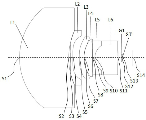
[0090] For the structural diagram of the external lens provided by the first embodiment of the present invention, please refer to figure 1 , the external lens includes in order from the object side to the imaging surface along the optical axis: the first lens L1, the second lens L2, the third lens L3, the fourth lens L4, the fifth lens L5, the sixth lens L6 and infrared filter Film G1, stop ST.

[0091] The first lens L1 has positive refractive power, the object side S1 of the first lens is a convex surface, and the image side S2 of the first lens is a concave surface;

[0092] The second lens L2 has negative refractive power, the object side S3 of the second lens is concave at the near optical axis, and the image side S4 of the second lens is convex at the near optical axis;

[0093] The third lens L3 has a negative refractive power, the object side S5 of the third lens is a convex surface, and the image side S6 of the third lens is a concave surface;

[0094] The fourth le...

no. 2 example

[0108] For the structural schematic diagram of the external lens provided in this embodiment, please refer to Figure 6 , the external lens includes in order from the object side to the imaging surface along the optical axis: the first lens L1, the second lens L2, the third lens L3, the fourth lens L4, the fifth lens L5, the sixth lens L6 and infrared filter Film G1, stop ST.

[0109] The first lens L1 has positive refractive power, the object side S1 of the first lens is a convex surface, and the image side S2 of the first lens is a concave surface;

[0110] The second lens L2 has positive refractive power, the object side S3 of the second lens is concave at the near optical axis, and the image side S4 of the second lens is convex at the near optical axis;

[0111] The third lens L3 has negative refractive power, the object side S5 of the third lens is concave at the near optical axis, and the image side S6 of the third lens is concave;

[0112] The fourth lens L4 has posit...

no. 3 example

[0126] For the structural schematic diagram of the external lens provided in this embodiment, please refer to Figure 11 , the external lens includes in order from the object side to the imaging surface along the optical axis: the first lens L1, the second lens L2, the third lens L3, the fourth lens L4, the fifth lens L5, the sixth lens L6 and infrared filter Film G1, stop ST.

[0127] The first lens L1 has positive refractive power, the object side S1 of the first lens is a convex surface, and the image side S2 of the first lens is a concave surface;

[0128] The second lens L2 has positive refractive power, the object side S3 of the second lens is concave at the near optical axis, and the image side S4 of the second lens is convex at the near optical axis;

[0129] The third lens L3 has negative refractive power, the object side S5 of the third lens is concave at the near optical axis, and the image side S6 of the third lens is concave;

[0130] The fourth lens L4 has posi...


PUM


Abstract

The invention provides an external lens, which sequentially comprises a first lens, a second lens, a third lens, a fourth lens, a fifth lens, a sixth lens and a diaphragm from an object side to an imaging surface along an optical axis, wherein the first lens has positive focal power, the object side surface of the first lens is a convex surface, and the image side surface of the first lens is a concave surface; the second lens has focal power, the object side surface of the second lens is a concave surface near the optical axis, and the image side surface of the second lens is a convex surface near the optical axis; the third lens has negative focal power, and the image side surface of the third lens is a concave surface; the fourth lens has positive focal power, and the object side surface of the fourth lens is a convex surface; the fifth lens and the sixth lens form a cemented lens group, the fifth lens has negative focal power, and the image side surface of the fifth lens is a concave surface; the sixth lens has negative focal power, the object side surface of the sixth lens is a convex surface, and the image side surface of the sixth lens is a convex surface; the external lens satisfies the following conditional expressions: 0.1 < f/TTL < 0.2, wherein f represents the effective focal length of the external lens, and TTL represents the total optical length of the external lens.

Description

technical field [0001] The invention relates to the technical field of lens imaging, in particular to an external lens. Background technique [0002] At present, with the popularization of portable electronic devices (such as smart phones, tablets, and cameras), coupled with the popularity of social, video, and live broadcast software, people are more and more fond of photography, so there is an external lens solution In order to achieve specific effects, an external lens is attached to the mobile phone to achieve the effect that the mobile phone’s own lens cannot achieve. However, the existing external lens has low pixels and small aperture, resulting in poor effects achieved through the external lens. Contents of the invention [0003] Based on this, the object of the present invention is to provide an external lens, which at least has the characteristics of ultra-high pixel, large aperture, and portability. [0004] Embodiments of the present invention achieve the abov...

Claims


Application Information

Patent Timeline
Patent Type & Authority Applications(China)
IPC IPC(8): G02B13/00G02B13/18
CPCG02B13/0015G02B13/0045G02B13/006G03B30/00
Inventor 王义龙曾昊杰曾吉勇
Owner 常州联益光学有限公司
Why Eureka
Try Eureka