
Intelligent power distribution cabinet for power transmission and distribution network

A technology for power transmission and distribution and power distribution cabinets, which is applied in the direction of battery circuit devices, substation/power distribution device shells, substation/switchgear cooling/ventilation, etc. and other issues, to achieve the effect of being beneficial to the image of the city, avoiding collision with the cabinet, and improving safety

Pending Publication Date: 2021-11-02
ANHUI UNIV OF SCI & TECH
View PDF0 Cites 0 Cited by
  • Summary
  • Abstract
  • Description
  • Claims
  • Application Information

AI Technical Summary

Problems solved by technology

The power distribution cabinet next to the road is installed in the open air, and the top is prone to dust. If it is not cleaned in time, the outside of the power distribution cabinet will be dirty, which will affect the appearance of the city.
In the case of poor light, pedestrians and passing vehicles are likely to collide with the power distribution cabinet, and the safety in use needs to be improved
In low-lying places where water is easy to accumulate, or where there is a lot of rain in coastal cities and drainage is not timely, the power distribution cabinet next to the road will often be flooded and damaged, and the power distribution cabinet itself has no self-rescue ability.

Method used


Image

  • Intelligent power distribution cabinet for power transmission and distribution network
  • Intelligent power distribution cabinet for power transmission and distribution network
  • Intelligent power distribution cabinet for power transmission and distribution network

Examples


Embodiment Construction

[0027] The technical solutions of the present invention will be clearly and completely described below in conjunction with the embodiments. Apparently, the described embodiments are only some of the embodiments of the present invention, not all of them. Based on the embodiments of the present invention, all other embodiments obtained by persons of ordinary skill in the art without creative efforts fall within the protection scope of the present invention.

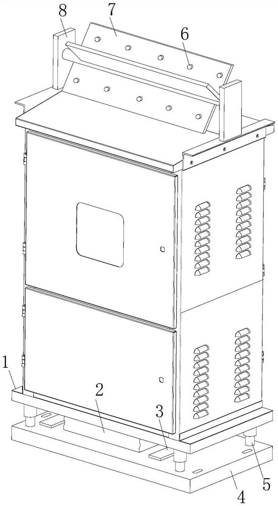
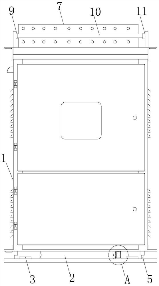
[0028] see Figure 1-5 As shown, an intelligent power distribution cabinet for a power transmission and distribution network includes a cabinet body 1, a cleaning mechanism is installed on the top of the cabinet body 1, and a protection mechanism is installed on the bottom of the cabinet body 1.

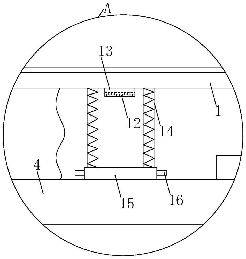
[0029] The protection mechanism includes an inflatable bag 2, a fixed plate 4 is installed on the bottom of the cabinet body 1, and a stabilizing mechanism is installed between the fixed plate 4 and the bottom of the cabinet body ...


PUM


Abstract

The invention relates to the field of power distribution cabinets, and concretely relates to an intelligent power distribution cabinet for a power transmission and distribution network. The cabinet comprises a cabinet body, a cleaning mechanism is mounted at the top of the cabinet body, a protection mechanism is mounted at the bottom of the cabinet body, the protection mechanism comprises an inflatable bag, a fixing plate is mounted at the bottom of the cabinet body, and a stabilizing mechanism is mounted between the fixing plate and the bottom of the cabinet body; and the top of the inflation bag is connected with the cabinet body, the bottom of the inflation bag is connected with the fixing plate, an air pump is installed at the bottom of the cabinet body, the air outlet end of the air pump is connected with the air inlet end of the inflation bag, a pressure relief valve is arranged on the inflation bag, the inflation bag is enlarged and expands, then the inflation bag jacks up the cabinet body, and the height of the cabinet body is increased, so accumulated water on the lower portion is not prone to entering the cabinet body, lines in the cabinet body are not prone to making contact with water, the cabinet body can achieve self rescue under the water accumulation condition, and the self-rescue cabinet can be suitable for being used in places where installation positions are low-lying, water accumulation is prone to occurring, or rainwater is much and drainage is not timely in coastal cities.

Description

technical field [0001] The invention relates to the field of power distribution cabinets, in particular to an intelligent power distribution cabinet for power transmission and distribution networks. Background technique [0002] The power distribution cabinet is the final equipment of the power distribution system. The power distribution cabinet is a general term for the motor control center. The power distribution cabinet is used in the occasions where the load is relatively scattered and there are few circuits; the motor control center is used in the occasions where the load is concentrated and there are many circuits. They distribute the electric energy of a certain circuit of the upper-level power distribution equipment to the nearest load. [0003] In the city, due to the influence of the building and the environment, as well as the location of people living, many power distribution cabinets are installed next to the road to help the work of public facilities. The pow...

Claims


Application Information

Patent Timeline
Patent Type & Authority Applications(China)
IPC IPC(8): H02B1/28H02B1/30H02B1/56B08B1/04B08B1/00H02J7/32G08B5/36
CPCH02B1/28H02B1/30H02B1/565H02J7/32G08B5/36B08B1/165B08B1/32
Inventor 卢可方娜
Owner ANHUI UNIV OF SCI & TECH
Learn More