Corrugated steel web PC box girder, inner supporting and outer pulling device and construction method of supporting at first and lining next
A corrugated steel web and box girder technology, applied in bridges, bridge construction, bridge parts, etc., can solve the problems of corrugated steel web buckling stability and prestressing efficiency difficult to balance, so as to improve the reuse rate and ensure buckling Stability and the effect of ensuring construction safety
- Summary
- Abstract
- Description
- Claims
- Application Information
AI Technical Summary
Problems solved by technology
Method used
Image
Examples
Embodiment 1
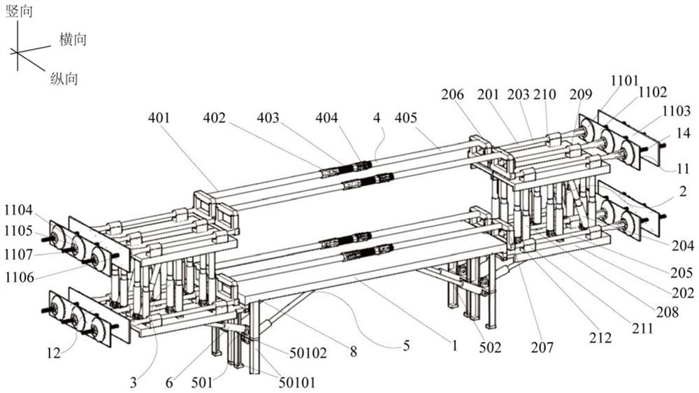
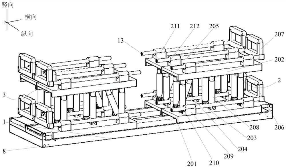
[0099] This embodiment provides a kind of internal support and external pulling device of corrugated steel web PC box girder, such as Figure 1 to Figure 8As shown, a PC box girder with corrugated steel webs has an inner brace and outer pull device, including a cross brace 1, and a right brace mechanism 2 and a left brace mechanism 3 are reversibly installed on both lateral sides of the brace plate 1. , the right brace mechanism 2 and the left brace mechanism 3 are oppositely arranged and have the same structure; a plurality of adjustable support rods 4 are arranged on the top of the cross brace plate 1, and the adjustable support rods 4 are installed on the right brace mechanism 2 and the left brace mechanism. between the mechanisms 3; a vertical support mechanism 5 is installed on the bottom surface of the cross brace plate 1;
[0100] The right stretching mechanism 2 includes an upper mounting plate 201 and a lower mounting plate 202 which are arranged in parallel and oppos...
Embodiment 2
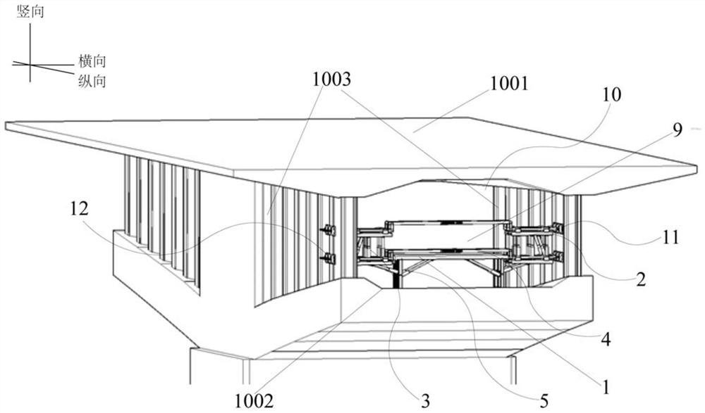
[0115] This embodiment provides a PC box girder with corrugated steel webs, such as Figure 1 to Figure 8 As shown, the corrugated steel web PC box girder 10 includes a box girder top plate 1001 and a box girder bottom plate 1002 arranged in parallel, and a pair of corrugated steel webs 1003 is vertically installed between the box girder top plate 1001 and the box girder bottom plate 1002, and also includes The installation space 9 for the inner brace and outer pull device is set between the box girder top plate 1001 and the box girder bottom plate 1002 inside the corrugated steel web PC box girder 10;
[0116] The installation space 9 for the inner brace and outer pull device is used to install the inner brace and outer pull device. In this embodiment, the inner brace and outer pull device adopts the inner brace and outer pull device of the corrugated steel web PC box girder in embodiment 1;
[0117] A pair of corrugated steel webs 1003 are respectively detachably installed w...
Embodiment 3
[0125] This embodiment provides a construction method of first bracing and then lining construction of a corrugated steel web PC box girder, which adopts the inner bracing and outer pulling device of the corrugated steel web PC box girder in Embodiment 2. The method comprises the following specific steps:
[0126] Step 1, build side span main girder:
[0127] Step 1.1, construction of bridge piers and side span girders;
[0128] Step 1.2, carry out ground treatment to the pier foundation, and construct the pier foundation and pier main body;
[0129] Step 1.3, set the side-span support, construct the side-span main beam on the side-span support, and complete the construction of the side-span main beam.
[0130] Step 2, construct the box girder floor of the 0# box girder and install the corrugated steel web:
[0131] Step 2.1, setting up the support on the top of the pier, and then preloading the support. In this embodiment, the purpose of the preloading of the support is to...
PUM
 Abstract
Description
Claims
Application Information
 - R&D
- Intellectual Property
- Life Sciences
- Materials
- Tech Scout
- Unparalleled Data Quality
- Higher Quality Content
- 60% Fewer Hallucinations
Browse by: Latest US Patents, China's latest patents, Technical Efficacy Thesaurus, Application Domain, Technology Topic, Popular Technical Reports.
© 2025 PatSnap. All rights reserved.Legal|Privacy policy|Modern Slavery Act Transparency Statement|Sitemap|About US| Contact US: help@patsnap.com


