Multilayer grating bearing cylinder and preparation method thereof

A load-bearing tube and grid tube technology, which is applied in the direction of attacking equipment, weight reduction, projectiles, etc., can solve the problems of overall buckling instability of the structure, increase in structural weight, and increased weight, and achieve high quality efficiency and buckling stability The effect of enhancing the performance and reducing the amount of materials

Active Publication Date: 2015-05-13
NAT UNIV OF DEFENSE TECH
View PDF5 Cites 26 Cited by
  • Summary
  • Abstract
  • Description
  • Claims
  • Application Information

AI Technical Summary

Problems solved by technology

[0005] However, large-scale cylinder structures including grid cylinders are prone to structural buckling and instability due to relatively thin walls. How to enhance stability is a key issue in the design of large-scale cylinder structures
Although increasing the wall thickness will improve the overall stability of the structure, it will lead to a substantial increase in the weight of the structure. Therefore, improving the stability of the cylinder structure under the premise of ensuring the weight of the structure is a technical difficulty today.
In the design of large aluminum alloy shell sections, it is often necessary to set intermediate frames at intervals of 40cm to 50cm in the shell section to improve the anti-instability ability of the shell section, but this intermediate frame design increases the weight

Method used


Image

  • Multilayer grating bearing cylinder and preparation method thereof
  • Multilayer grating bearing cylinder and preparation method thereof
  • Multilayer grating bearing cylinder and preparation method thereof

Examples


Embodiment 1

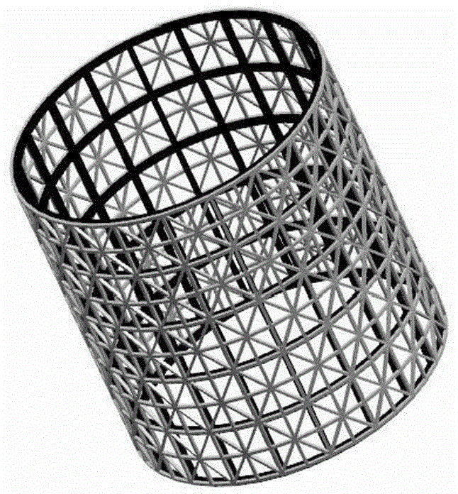
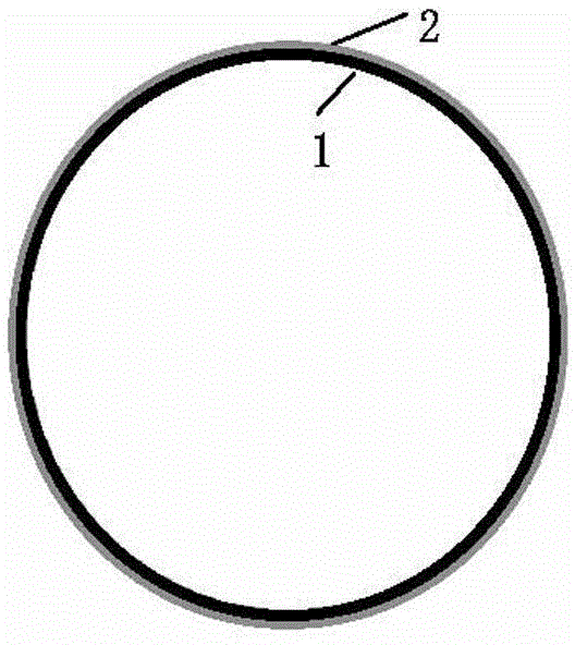
[0074] A kind of multi-layer grid load-bearing cylinder of the present invention, specifically double-layer grid load-bearing cylinder, such as Figure 1 ~ Figure 4 As shown, the multi-layer grid bearing cylinder is formed by nesting the inner grid cylinder 1 and the outer grid cylinder 2 . The grid of the inner grid cylinder 1 is sparse, and the grid of the outer grid cylinder 2 is relatively dense.

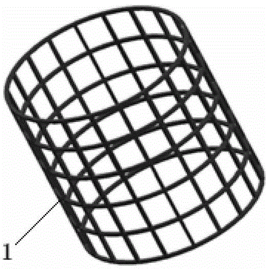
[0075] In this example, if image 3 and Figure 5 As shown, the unit grid configuration of the inner grid cylinder 1 is square. The inner grid tube 1 is composed of circumferential ribs and longitudinal ribs intersecting. In the cylindrical surface of the cylinder, the angle θ between the circumferential ribs and the circumference of the cylinder is 0°, and the angle between the longitudinal ribs and the circumference of the cylinder is 0°. θ is 90°. The inner grill tube 1 of the square grid has 6 circumferential ribs and 20 longitudinal ribs in total. Both are 5mm. The sp...

Embodiment 2

[0087] A kind of multi-layer grid load-bearing cylinder of the present invention is specifically a three-layer grid load-bearing cylinder, such as Figure 6 ~ Figure 10 As shown, the multi-layer grid bearing cylinder includes an inner grid cylinder 1 , a middle grid cylinder 3 and an outer grid cylinder 2 nested in sequence from the inside to the outside. The unit grid configurations of the three single-layer grid cylinders are similar, the grid structure of the inner grid cylinder 1 is the sparsest, the grid structure of the middle grid cylinder 3 is denser, and the grid structure of the outer grid cylinder 2 is relatively dense. most dense.

[0088] In this example, if Figure 8 As shown, the unit grid configuration of the inner grid cylinder 1 is rhombus. The inner grid tube 1 includes a grid, a top ring and a bottom ring. The grid is located between the top ring and the bottom ring. The grid is composed of the third spiral rib and the fourth spiral rib. for the circular...

Embodiment 3

[0103] A kind of multi-layer grid load-bearing cylinder of the present invention, specifically double-layer grid load-bearing cylinder, such as Figure 12 to Figure 15 As shown, the double-layer grid bearing cylinder is formed by nesting the inner grid cylinder 1 and the outer grid cylinder 2 . The grid of the inner grid cylinder 1 is sparse, and the grid of the outer grid cylinder 2 is relatively dense.

[0104] In this example, if Figure 14As shown, the unit grid configuration of the inner grid cylinder 1 is hexagonal. The inner grid cylinder 1 includes a grid, a top ring and a bottom ring. The grid is located between the top ring and the bottom ring. The grid is composed of discontinuous ring ribs, discontinuous third helical ribs and discontinuous fourth helical ribs. , both top and bottom rings are circumferential ribs. In the cylindrical surface of the cylinder, the angle θ between the discontinuous circumferential rib and the circumference of the cylinder is 0°, and...


PUM

PropertyMeasurementUnit
thicknessaaaaaaaaaa
widthaaaaaaaaaa
thicknessaaaaaaaaaa

Abstract

The invention discloses a multilayer grating bearing cylinder and a preparation method thereof. The multilayer grating bearing cylinder is formed by nesting at least two single-layer grating cylinders, and the densities of the meshes of the adjacent single-layer grating cylinders are different. The preparation method for the multilayer grating bearing cylinder made from a composite material comprises the following steps: producing a wood pattern for casting a soft mode, producing a silicon rubber soft mode, assembling a mould, winding the soft mode in an assistance manner, carrying out vacuum bag moulding, demoulding and carrying out after-treatment, and integrally moulding the multilayer grating bearing cylinder; or preparing the single-layer grating cylinders according to the steps, and then assembling the single-layer grating cylinders into the multilayer grating bearing cylinder. The preparation method for the multilayer grating bearing cylinder made from metal or engineering plastic comprises the following steps: preparing a casting mould for the disassembly components of the single-layer grating cylinders, melting and casting, welding, and then assembling the single-layer grating cylinders into the multilayer grating bearing cylinder; or moulding in one step by a 3D printing technology. The multilayer grating bearing cylinder has the characteristics of good structural stability, light mass, high mechanical properties, difficulty of structural overall buckling instability, simple and practicable preparation method, and low cost.

Description

technical field [0001] The invention belongs to the field of load-bearing structure design, and relates to the structure design of ultra-light material grids, in particular to a multi-layer grid load-bearing cylinder and a preparation method thereof. Background technique [0002] The high-performance and lightweight technology of structural parts has become a research hotspot in the field of aerospace. In order to make rockets, missiles, airplanes and other aircraft have excellent performance, such as long range, high speed, strong maneuverability, etc., the lightweight components of these aircraft have become an important development trend. Important technical measures for structural lightweight include the adoption of structural configurations with high load-bearing efficiency and the realization of composite materials for rocket bodies, projectile bodies, and cabins. In previous designs, aluminum alloy was often selected as the first choice material for manufacturing air...

Claims


Application Information

Patent Timeline
Patent Type & Authority Applications(China)
IPC IPC(8): B64C1/06F42B15/00B29C70/44
CPCY02T50/40
Inventor 江大志郑青鞠苏张鉴炜黄春芳肖加余
Owner NAT UNIV OF DEFENSE TECH
Why Eureka
Try Eureka