Air suction non-return assembly and scroll compressor comprising same

A technology for compressors and components, applied in the field of compressors, can solve the problems of increased suction resistance, energy efficiency, and increased compressor power consumption, so as to reduce suction resistance, increase constraints and positioning, and improve operation reliability. sexual effect

Active Publication Date: 2021-11-05
ZHUHAI GREE REFRIGERATION TECH CENT OF ENERGY SAVING & ENVIRONMENTAL PROTECTION
View PDF9 Cites 0 Cited by
  • Summary
  • Abstract
  • Description
  • Claims
  • Application Information

AI Technical Summary

Problems solved by technology

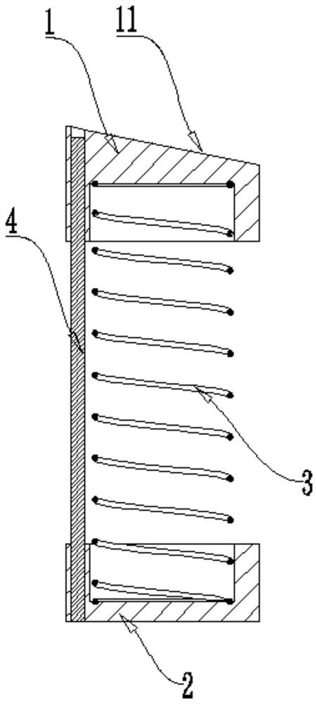
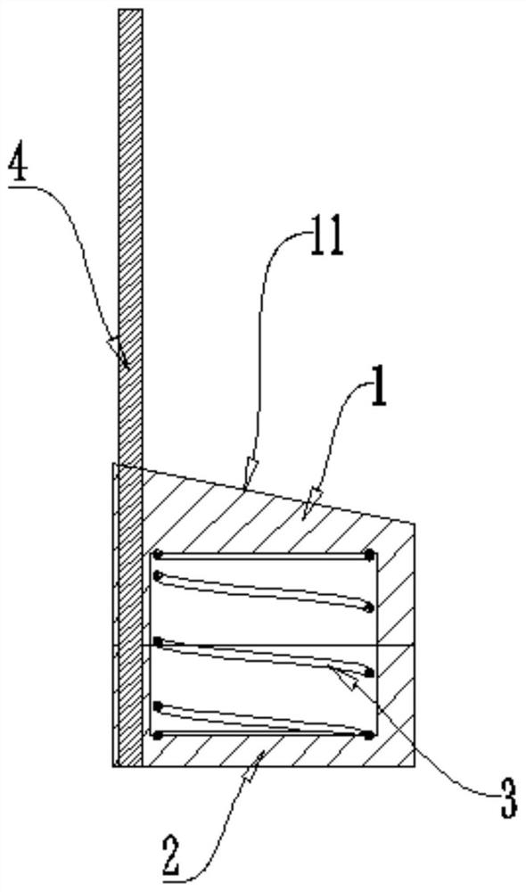
[0002] For the current traditional scroll compressor technology, the suction check structure is generally placed directly under the suction port. When the compressor is running, the gas entering from the compressor suction port enters the pump body at the suction check. The suction port is compressed. According to the current traditional structure of the scroll compressor, the upper end of the suction check assembly is perpendicular to the suction direction. This structure will cause the gas entering the suction port to be at the upper end of the suction check. Produces a reverse impact, resulting in increased suction resistance, increased compressor power consumption, and increased energy efficiency
At the same time, the traditional suction check assembly is an unconstrained part, which causes the part to rotate or tilt in the suction passage of the fixed scroll, resulting in collision between the part and the fixed scroll, Generates vibration noise while increasing compressor instability

Method used


Image

  • Air suction non-return assembly and scroll compressor comprising same
  • Air suction non-return assembly and scroll compressor comprising same
  • Air suction non-return assembly and scroll compressor comprising same

Examples


Embodiment Construction

[0039] In order to make the purpose, technical solutions and advantages of the embodiments of the present invention clearer, the technical solutions in the embodiments of the present invention will be clearly and completely described below in conjunction with the drawings in the embodiments of the present invention. Obviously, the described embodiments It is a part of embodiments of the present invention, but not all embodiments. Based on the embodiments of the present invention, all other embodiments obtained by persons of ordinary skill in the art without making creative efforts belong to the protection scope of the present invention.

[0040] Terms used in the embodiments of the present invention are only for the purpose of describing specific embodiments, and are not intended to limit the present invention. The singular forms "a", "said" and "the" used in the embodiments of the present invention and the appended claims are also intended to include plural forms, unless the ...


PUM


Abstract

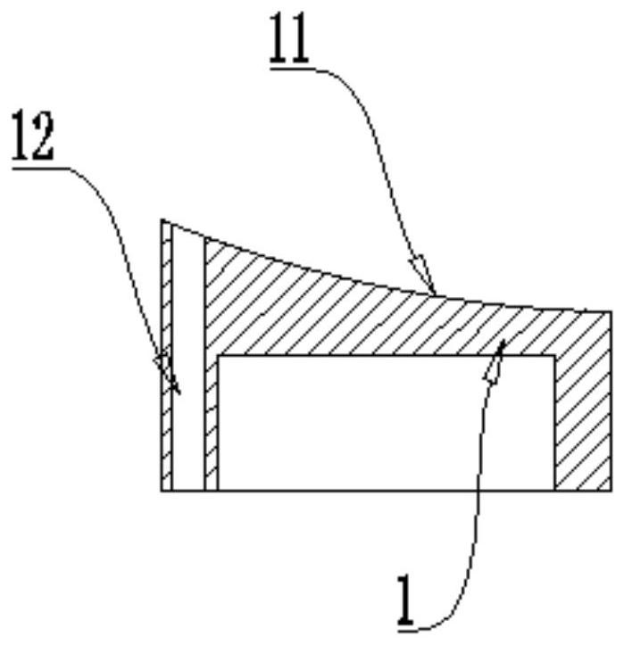
The invention provides an air suction non-return assembly and a scroll compressor comprising the same. The air suction non-return assembly is used for being arranged at an air suction port of the compressor to prevent air suction backflow and comprises an upper cover, a base and an elastic piece, and a flow guide structure for guiding air flow sucked by the air suction port is formed at the top of the upper cover; the base and the upper cover are oppositely arranged; the elastic piece is arranged between the upper cover and the base and can provide thrust for the upper cover; and the upper cover has a first state for blocking an air suction port of the compressor and a second state for opening the air suction port, the upper cover can be kept in the first state under the thrust action of the elastic piece, and the upper cover can be kept in the second state under the thrust action of air flow sucked by the air suction port. The air suction non-return assembly has the air suction guiding function, the upper cover has the positioning function, the function of reducing air suction resistance is achieved by guiding air, irregular movement of parts in the operation process is avoided by increasing constraint and positioning, and the operation reliability of the compressor is improved.

Description

technical field [0001] The invention relates to the technical field of compressors, in particular to an air suction non-return assembly and a scroll compressor including the same. Background technique [0002] For the current traditional scroll compressor technology, the suction check structure is generally placed directly under the suction port. When the compressor is running, the gas entering from the compressor suction port enters the pump body at the suction check. The suction port is compressed. According to the current traditional structure of the scroll compressor, the upper end of the suction check assembly is perpendicular to the suction direction. This structure will cause the gas entering the suction port to be at the upper end of the suction check. A reverse impact is generated, resulting in an increase in suction resistance, an increase in power consumption of the compressor, and an increase in its energy efficiency. At the same time, the traditional suction ch...

Claims


Application Information

Patent Timeline
Patent Type & Authority Applications(China)
IPC IPC(8): F04C29/12F04C18/02
CPCF04C29/128F04C18/0215
Inventor 龙孝天方琪刘双来
Owner ZHUHAI GREE REFRIGERATION TECH CENT OF ENERGY SAVING & ENVIRONMENTAL PROTECTION
Why Eureka
Try Eureka