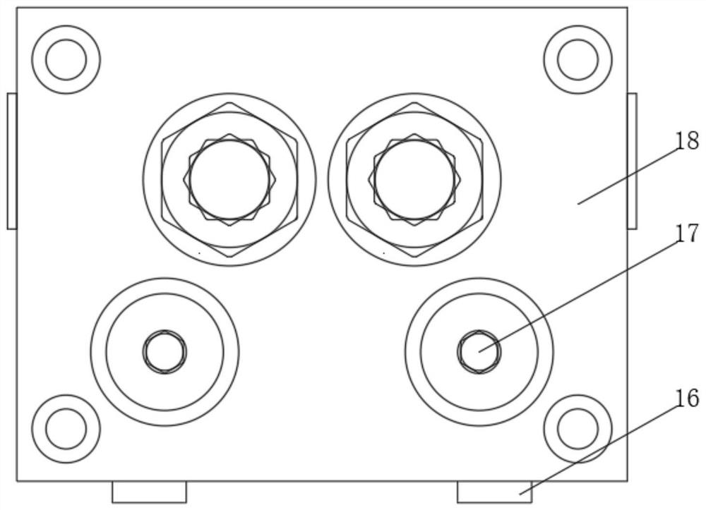
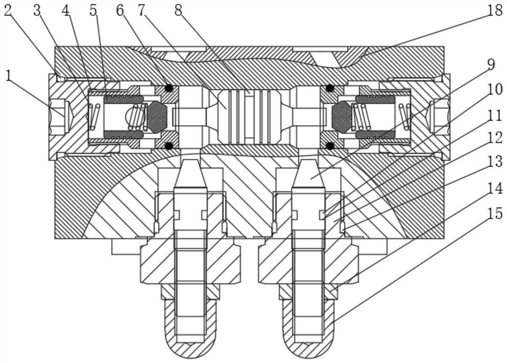
Hydraulic lock assembly capable of adjusting flow

A hydraulic lock and adjustable technology, used in servo motor components, fluid pressure actuation devices, mechanical equipment, etc., can solve the problems of poor device sealing and inconvenient control and adjustment of flow rate, so as to increase sealing and avoid leakage. Effect

Pending Publication Date: 2021-11-05
宁波威森搏乐机械制造有限公司
View PDF0 Cites 0 Cited by
  • Summary
  • Abstract
  • Description
  • Claims
  • Application Information

AI Technical Summary

Problems solved by technology

[0003] The purpose of the present invention is to solve the shortcomings of inconvenient control and adjustment of the flow in the circuit and the poor sealing of the device, and propose a hydraulic lock assembly with adjustable flow

Method used


Image

  • Hydraulic lock assembly capable of adjusting flow
  • Hydraulic lock assembly capable of adjusting flow

Examples


Embodiment Construction

[0018] The following will clearly and completely describe the technical solutions in the embodiments of the present invention with reference to the accompanying drawings in the embodiments of the present invention. Obviously, the described embodiments are only some, not all, embodiments of the present invention.

[0019] In describing the present invention, it should be understood that the terms "center", "longitudinal", "transverse", "length", "width", "thickness", "upper", "lower", "front", " Orientation indicated by rear, left, right, vertical, horizontal, top, bottom, inside, outside, clockwise, counterclockwise, etc. The positional relationship is based on the orientation or positional relationship shown in the drawings, and is only for the convenience of describing the present invention and simplifying the description, rather than indicating or implying that the referred device or element must have a specific orientation, be constructed and operated in a specific orientat...


PUM


Abstract

The invention relates to the technical field of hydraulic locks, in particular to a hydraulic lock assembly capable of adjusting flow. The hydraulic lock assembly solves the problems that the flow in a loop is inconvenient to control and adjust and the sealing performance of a device is poor. The hydraulic lock assembly comprises a valve body, an end sleeve cover is fixedly sleeved with the valve body, a first sealing ring is sleeved with the valve body, and an end sleeve cover is sleeved with the first sealing ring. A supporting sleeve is slidably sleeved with the end sleeve cover, a supporting sleeve is slidably sleeved with the valve body, a valve element is slidably sleeved with the supporting sleeve, a spring is arranged in the valve element, a plunger is slidably sleeved with the valve body, and the plunger and the valve element are slidably sleeved. By arranging a flow sleeve, a flow rod, a cap-shaped nut and other structures, the cap-shaped nut and the flow rod are rotated to do threaded motion so that the flow rod can stretch out and draw back in the flow sleeve, then the caliber of a flow channel in the contact position of the flow rod and the valve body can be changed, and then the flow can be adjusted and controlled.

Description

technical field [0001] The invention relates to the technical field of hydraulic locks, in particular to a flow-adjustable hydraulic lock assembly. Background technique [0002] Hydraulic lock, as the name suggests, is a "lock", which is to lock the circuit and prevent the oil from flowing in the circuit, as shown in the figure, to ensure that the cylinder can keep its position still even if there is a certain load from the outside. In the prior art, when the hydraulic lock assembly is in use, it is not convenient to control and adjust the flow rate in the circuit, and at the same time, the sealing performance of the device is poor, which may cause leakage. Therefore, it is necessary to improve the prior art. Contents of the invention [0003] The purpose of the present invention is to solve the shortcomings of inconvenient control and adjustment of the flow in the circuit and poor sealing performance of the device, and propose a flow-adjustable hydraulic lock assembly. ...

Claims


Application Information

Patent Timeline
Patent Type & Authority Applications(China)
IPC IPC(8): F15B13/01
CPCF15B13/01
Inventor 张志钊凌珠爱
Owner 宁波威森搏乐机械制造有限公司
Why Eureka
Try Eureka