Eureka AIR delivers breakthrough ideas for toughest innovation challenges, trusted by R&D personnel around the world.

Adjustable electric control valve element

A technology of spool and power adjustment, which is applied to valve details, valve devices, multi-way valves, etc., can solve the problems of complex structure and large volume, and achieve the effects of long service life, simple structure and low power consumption

Pending Publication Date: 2020-06-30
GULI (XIAMEN) TECH CO LTD
View PDF1 Cites 0 Cited by
  • Summary
  • Abstract
  • Description
  • Claims
  • Application Information

AI Technical Summary

Problems solved by technology

Such as: the patent with the publication number CN208919440U discloses a sensor faucet, the solenoid valve core needs to cooperate with the valve core seat to control the mixing water channel and the water outlet channel of the main body to be connected or disconnected, and the temperature adjustment channel is driven by the valve rod to move left and right to control Mixing cold and hot water to achieve temperature regulation, this structure occupies a large volume and complex structure, which cannot be realized in the space of an ordinary faucet body

Method used


Image

  • Adjustable electric control valve element
  • Adjustable electric control valve element
  • Adjustable electric control valve element

Examples


Embodiment 1

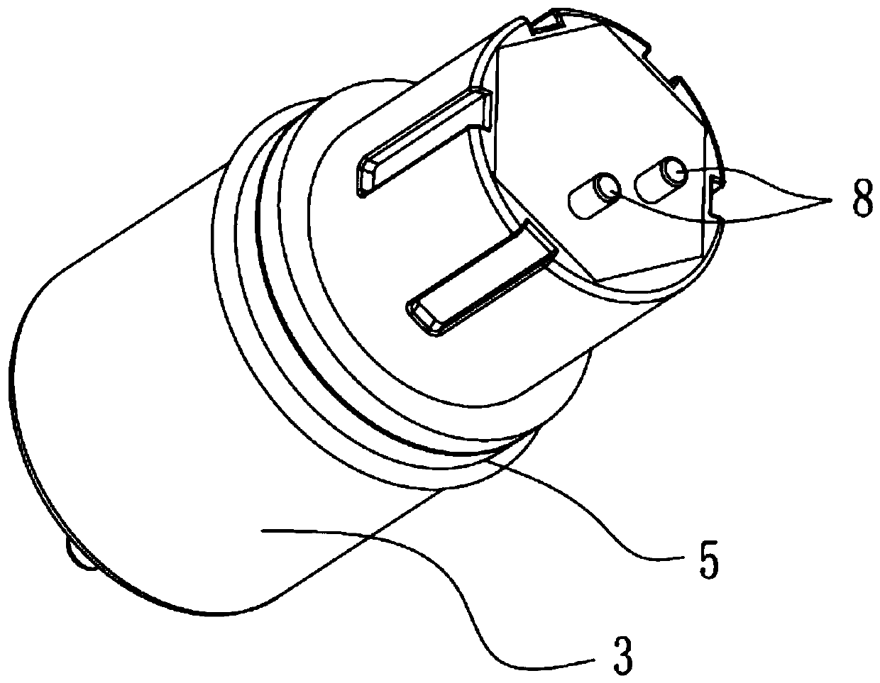
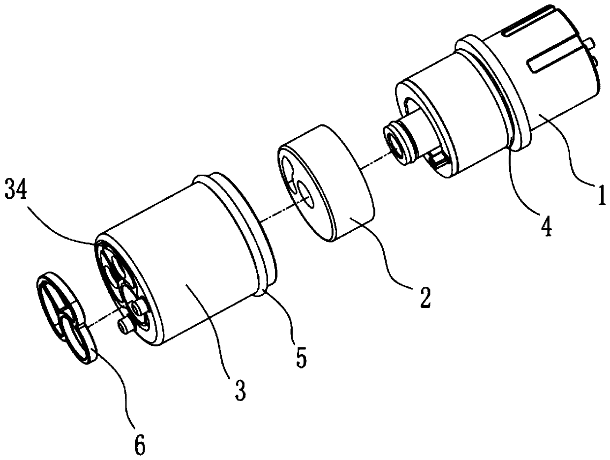
[0054] Such as Figure 2-11 As shown, this embodiment discloses an electronically controlled spool of a flow regulating type. It includes a pulse valve, a water diversion dial 3, a body sleeve 3 and several sealing rings.

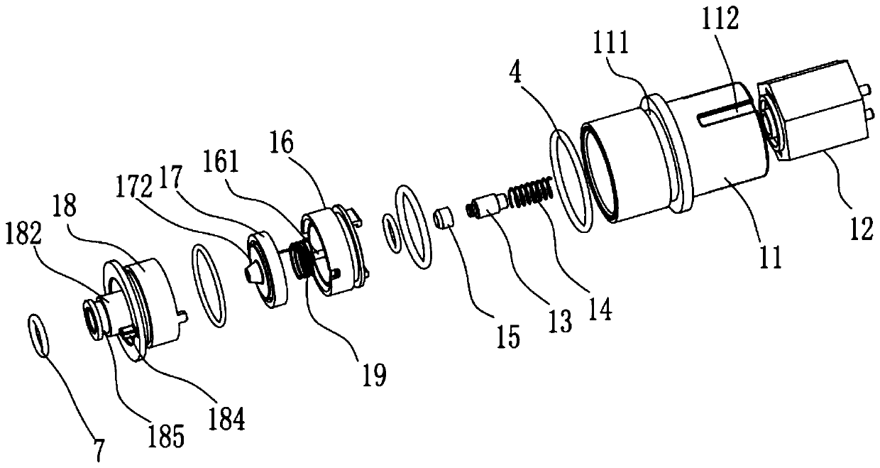
[0055]The pulse valve of the present embodiment selects bistable pulse valve 1, and its structure is as follows image 3 shown. Bistable pulse valve 1 includes: shell 11, coil iron core group 12, moving iron core 13, return spring 14, plug 15, upper valve seat 16, rubber membrane 17, lower valve seat 18 and anti-blocking needle spring 19 .

[0056] to combine Figure 5 As shown, the shell 11 is hollow inside, and the inner wall surface is smooth. The coil core set 12 is installed at one end inside the casing 11 , the end of the coil core set 12 is connected to the docking terminal 8 , and the docking terminal 8 extends out of the casing 11 to connect with the external control circuit structure. The moving iron core 13 is installed inside the coil iron...

Embodiment 2

[0066] Such as Figures 12 to 16 As shown, this embodiment discloses an electronically controlled spool of a thermostat type.

[0067] The difference between this embodiment and the first embodiment is that: the body cover 3 is provided with two body water inlets 31 , namely a cold water inlet 311 and a hot water inlet 312 .

[0068] The electronically controlled valve core of this embodiment can realize the functions of controlling the on-off of the water source and adjusting the water temperature.

[0069] The principle of controlling the on-off of the water source is the same as that in the first embodiment.

[0070] The principle of controlling the water temperature is as follows: the cold water inlet 311 is connected with the cold water pipe, and the hot water inlet 312 is connected with the hot water pipe. Turn the bistable pulse valve 1 so that the water diversion dial 2 fixedly connected to it rotates relative to the body sleeve 3 fixed on the external parts, as Fi...


PUM


Abstract

The invention discloses an adjustable electric control valve element. The adjustable electric control valve element comprises a pulse valve, a water diversion rotary disc and a body sleeve; a valve body water inlet and a valve body water outlet are formed in one end of the pulse valve, and a butt joint terminal is arranged at the other end of the pulse valve; the water diversion rotary disc is fixedly arranged on the pulse valve, a water diversion opening and a rotary disc water outlet are formed in the water diversion rotary disc, the water diversion opening communicates with the valve body water inlet in a sealed mode, and the rotary disc water outlet communicates with the valve body water outlet in a sealed mode; and the body sleeve is arranged on the water diversion rotary disc in a sleeving mode and is rotationally connected with the water diversion rotary disc in a sealed mode, a plurality of body water inlets and a body water outlet are formed in the body sleeve, the body wateroutlet communicates with the rotary disc water outlet, and in the relative rotation process of the water diversion rotary disc and the body sleeve, the water diversion opening at least partially communicates with the water inlets. The adjustable electric control valve element is small in size, can be matched with a mechanical ceramic valve element, and can adjust the flow or the cold and hot watermixing proportion.

Description

technical field [0001] The invention relates to an electromagnetic valve core, in particular to an adjustable electric control valve core. Background technique [0002] The water outlet control of the existing faucet generally adopts a mechanical ceramic valve core, which is operated by manual lifting and rotation, so as to realize the on-off of the water flow, the adjustment of the flow rate, and the adjustment of the mixing ratio of hot and cold water. [0003] With the development of the bathroom industry, the induction faucet has partially replaced the ordinary faucet, but the processing of the accessories of the induction faucet is much more complicated than that of the ordinary faucet. The existing induction faucet is equipped with a solenoid valve core, which needs to be integrated with other components. Cooperate to realize the adjustment of water flow channel, flow size or mixing of cold and hot water. Such as: the patent with the publication number CN208919440U di...

Claims


Application Information

Patent Timeline
Patent Type & Authority Applications(China)
IPC IPC(8): F16K11/24F16K11/074F16K31/40F16K31/06
CPCF16K11/074F16K11/24F16K31/0655F16K31/0675F16K31/402
Inventor 陈添育孙廷委胡浩玮
Owner GULI (XIAMEN) TECH CO LTD
Why Eureka
Eureka Blog
Learn More