Compactor for highway construction test
A technology of test and compaction instrument, which is applied in the preparation of test samples, instruments, scientific instruments, etc. It can solve the problems of inconveniently taking out core samples, complicated test operation, and inconvenient adjustment of mixed core samples, etc.
- Summary
- Abstract
- Description
- Claims
- Application Information
AI Technical Summary
Problems solved by technology
Method used
Image
Examples
Embodiment 1
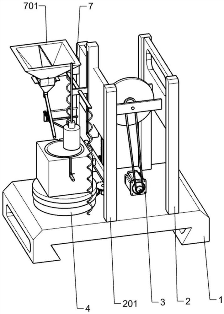
[0031] A compaction instrument for road construction test, such as figure 1As shown, it includes a base 1, a bracket 2, a bracket 201, a horizontal plate 2011, a horizontal plate 2012, a horizontal bar 202, a motor 3, a pulley 301, a toggle assembly, a belt 302, and a pressing assembly And the pressure measuring barrel assembly, the upper side of the base 1 is equipped with a bracket 2, a bracket 2 201 and a motor 3, the bracket 2 and the bracket 201 are fixed side by side on the upper side of the base 1, and the bracket 2 is located on the right side of the bracket 2 201 The first horizontal plate 2011 and the second horizontal plate 2012 are fixedly connected to the lower end of the second bracket 201, the first horizontal plate 2011 is located above the second horizontal plate 2012, the motor 3 is fixedly connected to the upper side of the base 1, and the motor 3 is located between the first bracket 2 and the second bracket In the middle of 201, the output shaft end of moto...
Embodiment 2
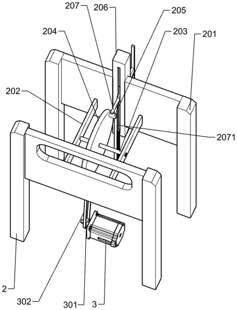
[0034] On the basis of Example 1, such as Figure 2-6 As shown, the toggle assembly includes a rotating shaft 203, a wheel 204, and a dial 205. The front and rear ends of the rotating shaft 203 are rotatably connected to the middle of the cross bar 202, and the wheel 204 is fixedly connected to the middle of the rotating shaft 203. Rotating shaft 1 203 passes through the center of the wheel 204. Two dials 205 are arranged symmetrically along the center of the wheel 204. The dial 205 is fixedly connected to the peripheral edge of the wheel 204. The dial 205 touches the pressing assembly.
[0035] After the power is transmitted to the belt one 302, the belt one 302 will drive the wheel 204 to rotate, and the dial 205 on the wheel 204 will also rotate accordingly, and the dial 205 will touch the pressing assembly during the movement, so that It plays a role in allowing the rotation of the wave device to drive the pressing component.
[0036] The pressing assembly includes a stra...
Embodiment 3
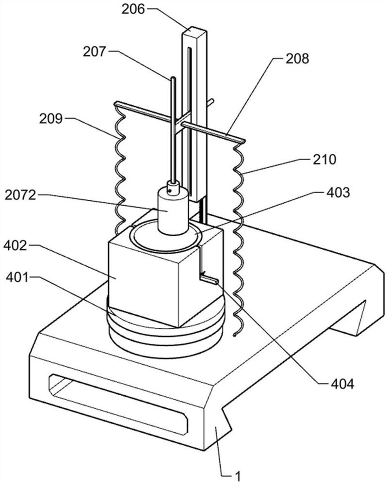
[0045] On the basis of Example 2, such as Figure 7-10 Shown, also include strong spring one 209, cross bar two 208 and strong spring two 210, cross bar two 208 are fixedly connected in the middle part of T slide bar 207, and the front and rear ends of cross bar two 208 are respectively fixedly connected with strong spring one 209 and strong spring two 210, the lower end of strong spring one 209 and strong spring two 210 is fixedly connected on base 1 upper side.
[0046] In order to make the crushing post 2072 have greater strength in the process of smashing down, the two ends of the cross bar two 208 are connected with a strong spring one 209 and a strong spring two 210, and the lower ends of the strong spring one 209 and the two strong spring 210 are connected on the On the base 1, in this way, a greater downward force can be applied to the crushing column 2072, which can make the core sample crushed more firmly.
[0047] Also include small support plate 6, shaft two 601, ...
PUM
 Abstract
Description
Claims
Application Information
 - R&D
- Intellectual Property
- Life Sciences
- Materials
- Tech Scout
- Unparalleled Data Quality
- Higher Quality Content
- 60% Fewer Hallucinations
Browse by: Latest US Patents, China's latest patents, Technical Efficacy Thesaurus, Application Domain, Technology Topic, Popular Technical Reports.
© 2025 PatSnap. All rights reserved.Legal|Privacy policy|Modern Slavery Act Transparency Statement|Sitemap|About US| Contact US: help@patsnap.com


