Device for automatically locating railway vehicle

A technology of locomotives and phases, applied in the direction of vehicle control routing devices, transportation and packaging, railway car body parts, etc.

Inactive Publication Date: 2004-01-28
SIEMENS AG
View PDF0 Cites 0 Cited by
  • Summary
  • Abstract
  • Description
  • Claims
  • Application Information

AI Technical Summary

Problems solved by technology

[0004] The technical problem to be solved by the present invention is to further improve the self-positioning device of the aforementioned railcar, so that even when the locomotive has a single antenna or receiving ante

Method used


Image

  • Device for automatically locating railway vehicle
  • Device for automatically locating railway vehicle
  • Device for automatically locating railway vehicle

Examples


Embodiment Construction

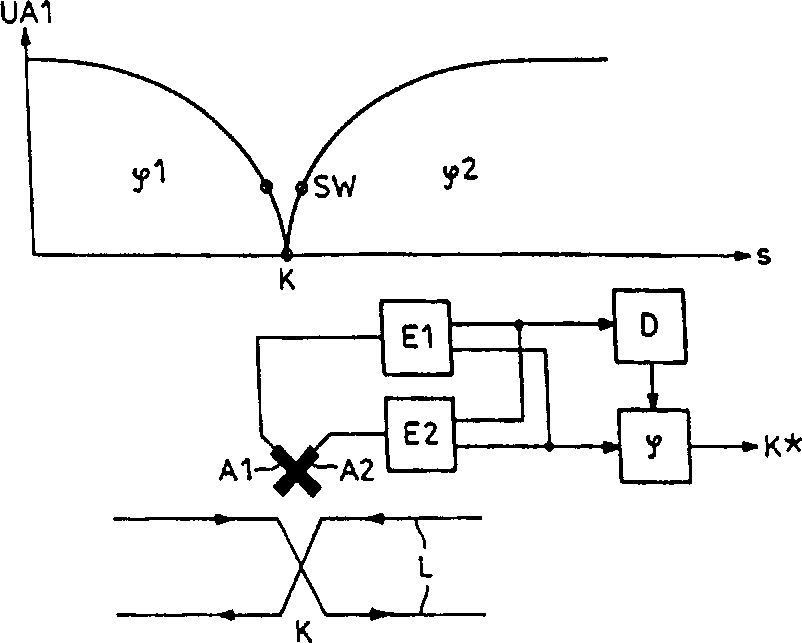
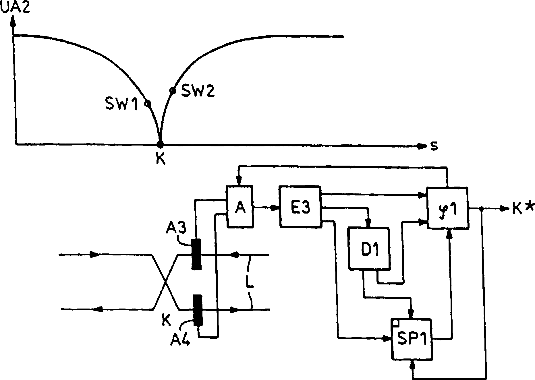
[0012] The figure shows a partial schematic diagram of a sensor wire L laid between the track rails (not shown), through which a signal current flows in the direction of the arrow. This signal current forms a magnetic field around the sensor wire which is picked up by the cross receiving antennas A1, A2 of the locomotive running on the track. At the line crossing point K, where a locomotive should be detected as it passes, the change in the geometry of the sensing conductors in the track towards the return conductors is significant. As can be seen from the illustrated variation of the receiving voltage UA1 of a receiving antenna on the locomotive side over the route S, the receiving voltage drops when the locomotive antenna approaches the line intersection in order to increase to the same value later. In this case, the phase of the received voltage changes by 180°, since the sensor line sections arranged at the bottom of the antenna have signal currents flowing in different di...


PUM


Abstract

On vehicles provided with a single reception antenna or with several adjacent reception antennas (A3, A4) coupled to the go-and-return lines of a track conductor (L), the phase angle of the reception voltage is retained when the reception level falls below a particular reception level (SW1). If the level (SW2) of the reception voltage rises again, the actual phase position of the reception voltage (UA3) can be compared with the retained reception voltage. When the phases of the reception voltages to be compared are in opposition, one concludes that the vehicle is passing over a track conductor crossing (K). When the phases of the reception voltages to be compared are the same, this indicates a passing transmission disturbance. The phase angle of the comparison voltage is preferably retained by a flywheel oscillator. The difference in time between actual reception voltage (UA3) and comparison voltage is preferably determined by evaluating the peak values of both voltages.

Description

technical field [0001] The invention relates to a self-positioning device for a rail vehicle traveling on a railway line which is divided into sections by means of crossing, externally fed sensor conductor loops. Background technique [0002] Such a device is known, for example, from DE-PS 11 76 698 . Therein, the self-positioning of the locomotive is reported in connection with a system for driving safety with a linear signal transmission between the locomotive and the railway line. This kind of locomotive is inductively coupled with the sensing wires laid on the track through the coupling frame, and the important data about locomotive control is transmitted from the remote console through the sensing wires. The coupling wire holders are arranged at an angle of 90° to each other and at a 45° angle to the sensing wire loop. By means of this line stand arrangement FM information can be received by or sent to the center even when passing through line crossing points. Furthe...

Claims


Application Information

Patent Timeline
IPC IPC(8): B61L3/22
CPCB61L3/225
Inventor 迈克尔·迈耶阿克塞尔·波斯伯格汉斯-乔基姆·沃恩霍尔茨
Owner SIEMENS AG
Why Eureka
Try Eureka