Portable automatic equipment maintenance platform

An automation equipment and maintenance platform technology, applied in workshop equipment, manufacturing tools, etc., can solve the problems of inconvenient placement of precision parts and tools, inconvenient storage and portability, inconvenient use, etc., to achieve easy portability, increased convenience, and easy storage Effect

Pending Publication Date: 2021-11-09
苏州恩次方智能科技有限公司
View PDF0 Cites 0 Cited by
  • Summary
  • Abstract
  • Description
  • Claims
  • Application Information

AI Technical Summary

Problems solved by technology

[0005] The purpose of the present invention is to provide a portable automation equipment maintenance platform to solve the problems in the above-mentioned background technology that it occupies a large space during storage, is inconvenient for storage and portability, and is inconvenient for placing precision parts and tools and when in use. The problem that requires a single person is inconvenient to use

Method used


Image

  • Portable automatic equipment maintenance platform
  • Portable automatic equipment maintenance platform
  • Portable automatic equipment maintenance platform

Examples


Embodiment 1

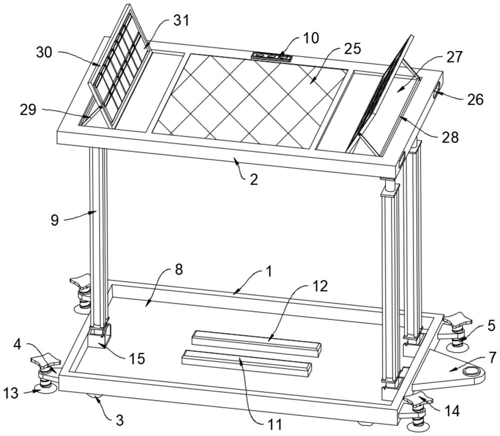
[0036] Embodiment 1, when the present invention is in use, the control panel 10 is used to control the rotation of the road wheels 3 or to pull the traction plate 7 to move the present invention, so that the present invention moves to a suitable position, which is convenient for carrying the present invention, and when moving After reaching the proper position, turn the support rod 5 by turning the handle 14, so that the foot pad 13 is in contact with the ground, avoid the movement of the base plate 1, and improve the stability of the base plate 1, lift the lifting platform 2 by the slot 26, and when lifted When lifting the platform 2, due to gravity, the slider 22 moves downward from the inside of the engaging groove 24, and moves to the inside of the chute 23, and continues to lift the lifting platform 2, so that the slider 22 is on the inside of the chute 23. Slide inside, and make the cylinder 9 tend to rotate along the fixed seat 15 in the vertical direction. When the cyli...

Embodiment 2

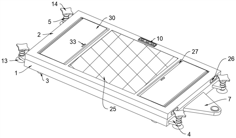
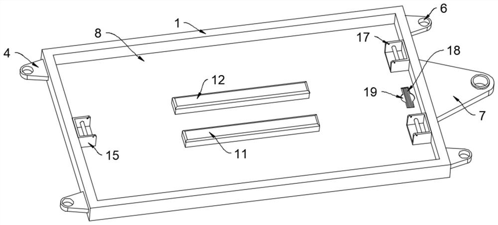
[0038] Embodiment 2, when the present invention is being stored and carried, the tool board 30 is pulled through the pull groove 33, so that the tool board 30 is rotated, so that the tool board 30 is parallel to the lifting platform 2, and the tool board 30 is lowered by rotating the support plate 29. To the inside of the concave groove 27, and make the canvas bag 31 contact with the lower surface of the concave groove 27, it is convenient to store the tool plate 30, and it is convenient to cover the canvas bag 31, and it is convenient to store tools and parts. The plate 10 closes the cylinder 9, so that the cylinder 9 drops to the lowest state, and the personnel get off the lifting platform 2, and pull the pin rod 18 from the inside of the pin hole 17, and place it in the inside of the placement groove 19, so as to facilitate alignment of the pin rod 18. storage, and through the groove 26, the lifting platform 2 is lifted, so that the slider 22 is separated from the snap-in gr...


PUM


Abstract

The invention relates to the technical field of equipment maintenance platforms, in particular to a portable automatic equipment maintenance platform. The portable automatic equipment maintenance platform comprises a bottom plate and a lifting platform, walking wheels are fixedly installed at the four corners of the lower surface of the bottom plate, a groove is formed in the middle of the upper surface of the bottom plate, air cylinders are evenly and rotationally installed in the groove, the upper ends of the air cylinders and the lower surface of the lifting platform are rotationally installed, the lifting platform is lifted through the air cylinders, a control panel is located on the lifting platform, single-person independent control is facilitated, cooperation of multiple persons is not needed, a tool plate is rotationally installed on the lifting platform, during maintenance, parts or tools can be conveniently stored through the tool plate, can be convenient to take and use, the air cylinders are folded in the groove during storage, storage is facilitated, the overall height of the device is reduced, and the convenience during carrying and the stability during fixing are improved by installing the walking wheels and supporting rods.

Description

technical field [0001] The invention relates to the technical field of equipment maintenance platforms, in particular to a portable automation equipment maintenance platform. Background technique [0002] Automation technology is widely used in industry, agriculture, military, scientific research, transportation, commerce, medical care, service and family, etc. The use of automation technology can not only save people from heavy physical labor, some mental work, and harsh and dangerous working environments. It can be liberated from the environment, and can expand the functions of human organs, greatly improve labor productivity, and enhance the ability of human beings to understand and transform the world. Automation is specialized in the research and development, production and sales of intelligent automatic control, digital, networked controllers and sensors. A high-tech company, its many functional modules and perfect embedded solutions can meet the individual needs of ma...

Claims


Application Information

Patent Timeline
Patent Type & Authority Applications(China)
IPC IPC(8): B25H5/00
CPCB25H5/00
Inventor 李赛
Owner 苏州恩次方智能科技有限公司
Why Eureka
Try Eureka