
Novel rotary engraving assembly

A component and a new type of technology, applied in the field of metal stamping processing, can solve the problems of increased production cost, affecting production efficiency, poor variability, etc., and achieve the effect of low cost and simple structure

Inactive Publication Date: 2021-11-12
JOUDER PRECISION INDAL KUSN
View PDF7 Cites 0 Cited by
  • Summary
  • Abstract
  • Description
  • Claims
  • Application Information

AI Technical Summary

Problems solved by technology

However, the above methods have disadvantages, for example: (1) manual clamping and programming are required when using engraving machines or CNC electrical discharge equipment, which not only leads to longer production cycles, but also increases consumables, resulting in production costs. Increase; (2) When processing a single molding mold part, it is necessary to use a single mold part to emboss the text, but this molding method needs to process many mold parts when it is used for a long time, resulting in an increase in cost and poor interchangeability. It is cumbersome, and it takes a lot of time to replace it, which affects production efficiency; (3) The common rotary marking mechanism needs manual adjustment, but the adjustment is difficult and the operation is complicated; (4) Although the automatic rotary marking mechanism can fulfill most of the needs, However, its engraving sequence combination is single, and it cannot be jumped by a single character wheel, and its variable performance is poor.

Method used


Image

  • Novel rotary engraving assembly
  • Novel rotary engraving assembly
  • Novel rotary engraving assembly

Examples


Embodiment Construction

[0027] It should be noted that, in the case of no conflict, the embodiments in the present application and the features in the embodiments can be combined with each other.

[0028] In the description of the present application, it should be understood that the terms "center", "longitudinal", "transverse", "upper", "lower", "front", "rear", "left", "right", " The orientation or positional relationship indicated by "vertical", "horizontal", "top", "bottom", "inner", "outer", etc. is based on the orientation or positional relationship shown in the drawings, and is only for the convenience of describing the present application and Simplified descriptions do not indicate or imply that the device or element referred to must have a specific orientation, be constructed and operate in a specific orientation, and thus should not be construed as limiting the scope of protection of the present application. In addition, the terms "first", "second", etc. are used for descriptive purposes on...


PUM


Abstract

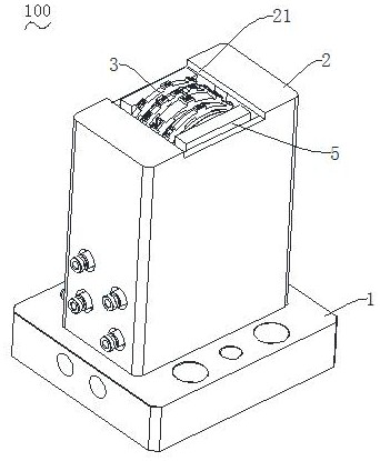
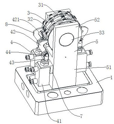
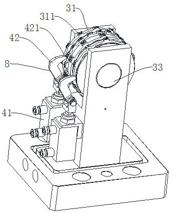
The invention relates to a novel rotary engraving assembly. The novel rotary engraving assembly comprises a shell; an engraving unit, wherein at least part of the engraving unit is arranged in the shell, the engraving unit comprises at least two character wheel pieces, and a plurality of engraving character dies are arranged on the circumferential surfaces of the character wheel pieces; and a shifting unit which comprises a shifting piece, wherein the shifting piece abuts against any character wheel piece under the action of external force so as to push the character wheel piece to rotate, so that the target engraving character die reaches the target position, jumping of the single character wheel piece is achieved, the structure is simple, and the cost is low.

Description

technical field [0001] The invention relates to a novel rotary marking component, which belongs to the technical field of metal stamping processing. Background technique [0002] In the traditional text forming technology, CNC engraving machines, CNC discharge equipment are generally used, individual mold parts are individually embossed for text forming, or automatic rotary engraving mechanisms are used. However, the above methods have disadvantages, for example: (1) manual clamping and programming are required when using engraving machines or CNC electrical discharge equipment, which not only leads to longer production cycles, but also increases consumables, resulting in production costs. Increase; (2) When processing a single molding mold part, it is necessary to use a single mold part to emboss the text, but this molding method needs to process many mold parts when it is used for a long time, resulting in an increase in cost and poor interchangeability. It is cumbersome,...

Claims


Application Information

Patent Timeline
Patent Type & Authority Applications(China)
IPC IPC(8): B41K1/12
CPCB41K1/12
Inventor 汪煜刚徐遵善何祥提
Owner JOUDER PRECISION INDAL KUSN
Learn More