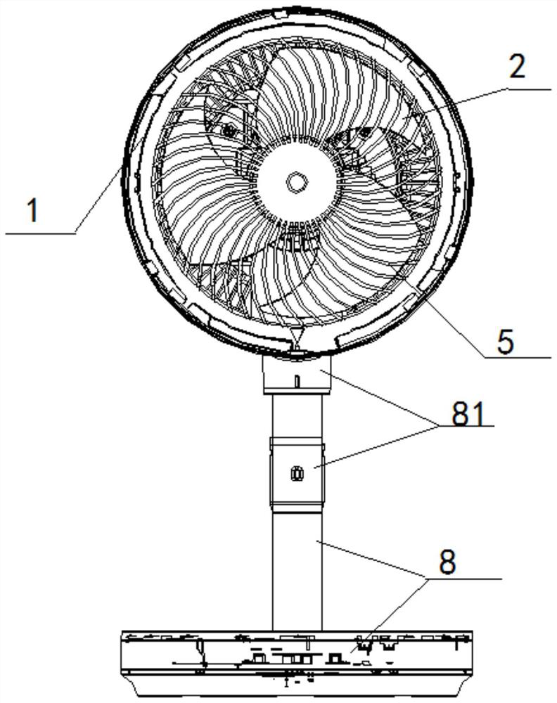
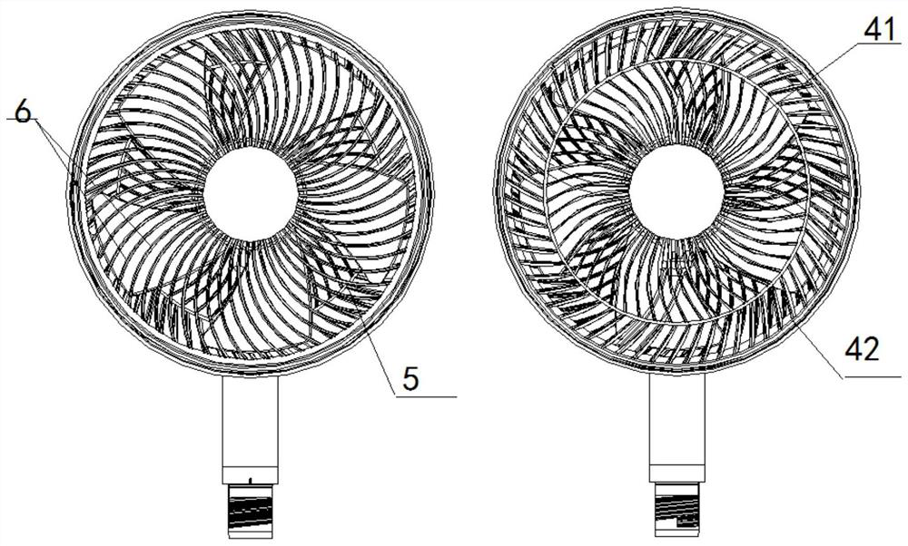
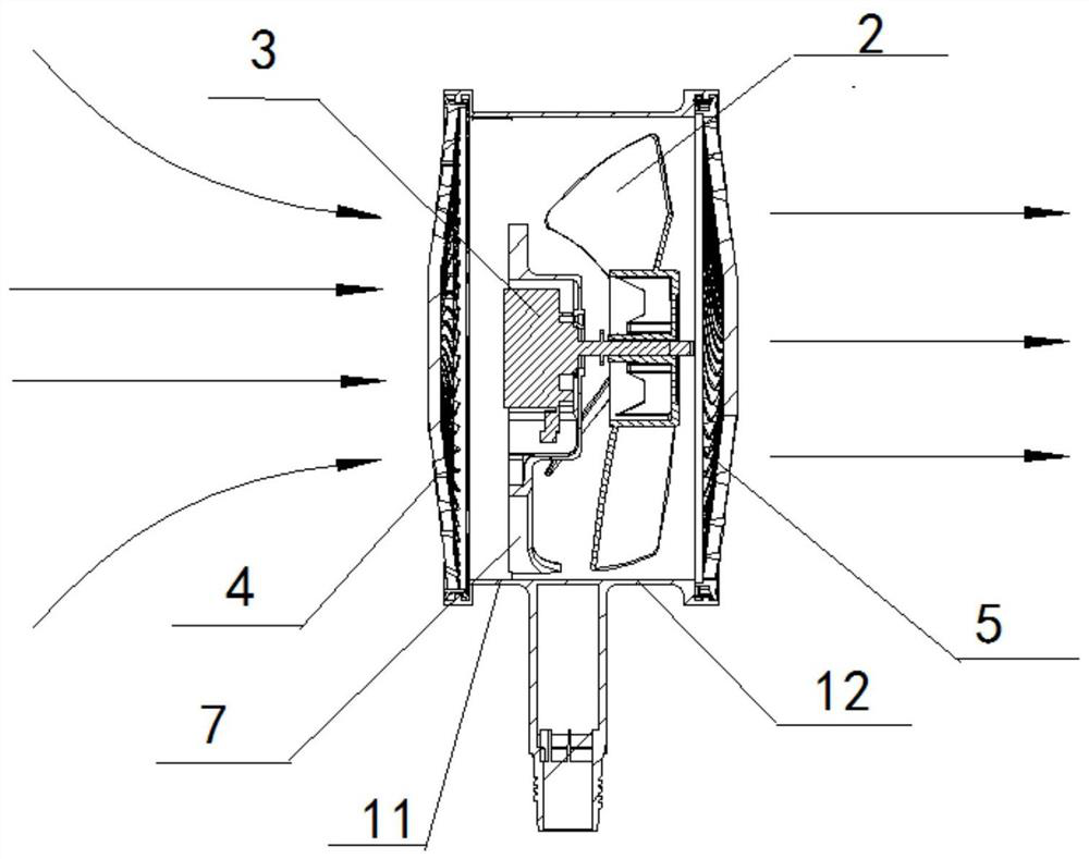
Air outlet device

A technology of air outlet device and air outlet direction, which is applied to pump devices, parts of pumping devices for elastic fluids, non-variable pumps, etc., and can solve the problem that the air outlet device cannot realize separate wind collection and air dispersion at the same time Function and other issues

Pending Publication Date: 2021-11-12
GREE ELECTRIC APPLIANCES INC
View PDF0 Cites 0 Cited by
  • Summary
  • Abstract
  • Description
  • Claims
  • Application Information

AI Technical Summary

Problems solved by technology

[0004] Therefore, the technical problem to be solved by the present invention is to overcome the defect that a single air outlet device i

Method used


Image

  • Air outlet device
  • Air outlet device
  • Air outlet device

Examples


Embodiment Construction

[0036] The technical solutions of the present invention will be clearly and completely described below in conjunction with the accompanying drawings. Apparently, the described embodiments are some of the embodiments of the present invention, but not all of them. Based on the embodiments of the present invention, all other embodiments obtained by persons of ordinary skill in the art without making creative efforts belong to the protection scope of the present invention.

[0037] In the description of the present invention, it should be noted that the terms "center", "upper", "lower", "left", "right", "vertical", "horizontal", "inner", "outer" etc. The indicated orientation or positional relationship is based on the orientation or positional relationship shown in the drawings, and is only for the convenience of describing the present invention and simplifying the description, rather than indicating or implying that the referred device or element must have a specific orientation, ...


PUM


Abstract

The invention provides an air outlet device. The air outlet device comprises an air duct, a power assembly and a mesh enclosure assembly; the power assembly is arranged in the air duct and comprises fan blades and a power piece which are connected, and the power piece is suitable for driving the fan blades to rotate in the first rotating direction or the second rotating direction which are opposite; the mesh enclosure assembly comprises a first mesh enclosure and a second mesh enclosure which are arranged at the two ends of the air duct respectively, the first mesh enclosure is correspondingly arranged in the air outlet direction when the fan blades rotate in the first rotating direction, the second mesh enclosure is correspondingly arranged in the air outlet direction when the fan blades rotate in the second rotating direction, the first mesh enclosure is suitable for diffusing and discharging the outlet airflow, and the second mesh enclosure is suitable for discharging the outlet airflow in a centralized mode. Through the arrangement, a user can adjust the rotating direction of the fan blades by controlling forward and reverse rotation of the power piece, then the air inlet side and the air outlet side at the two ends of the air duct can be switched; the air outlet mode of the air outlet device can be adjusted through arrangement of the first mesh enclosure for diffusing air and the second mesh enclosure for centralized air outlet at the two ends of the air duct correspondingly, and the defect that in the prior art, a single air outlet device cannot achieve the air gathering function and the air diffusing function at the same time is overcome.

Description

technical field [0001] The invention relates to the technical field of fans, in particular to an air outlet device. Background technique [0002] As a traditional fan category, floor fans generally use single-layer or double-layer fan blades, combined with metal or plastic mesh covers, to achieve air blowing and cooling. Because the fan blades are long in the radial direction and there is no diffuser fan, the air flow diffuses quickly after flowing out of the grille. Therefore, the floor fan has a wide blowing range and the blown wind is soft and comfortable, but its wind speed is relatively low and the air supply distance is relatively low. closer. Compared with the floor fan, the circulation fan has added structures such as turbine blades and diffuser air ducts, which can let the wind blow out in a spiral shape along a certain direction. With the stirring of the fan blades, a spiral columnar wind can finally be formed, and its wind speed is high. , The air supply distanc...

Claims


Application Information

Patent Timeline
IPC IPC(8): F04D25/08F04D29/52F04D29/70F04D29/54
CPCF04D25/08F04D29/522F04D29/703F04D29/541
Inventor 梁浩柳洲陈宇强黄少杰李亮范瑞鹏
Owner GREE ELECTRIC APPLIANCES INC
Why Eureka
Try Eureka