Control method, embedded machine and computer readable storage medium

A control method and computer technology, which are applied to airflow control elements, heating and ventilation control systems, heating methods, etc., can solve the problem of not being able to swing the blowing angle of the wind deflector in real time according to the user's position, so as to improve the air outlet range and reduce the Wind feeling, the effect of improving comfort

Active Publication Date: 2020-12-04
QINGDAO HAIER AIR CONDITIONING ELECTRONICS CO LTD +1
View PDF10 Cites 4 Cited by
  • Summary
  • Abstract
  • Description
  • Claims
  • Application Information

AI Technical Summary

Problems solved by technology

[0004] In order to solve the above-mentioned problems in the prior art, that is, in order to solve the problem that the existing embedding machine cannot swing the blowing angle of the wind deflector in real time according to the user's position, the present invention provides a control method, which is used in the embedding machine , the embedding machine has an air outlet panel, the bottom surface of the air outlet panel has an air inlet, and the side has a plurality of air outlets, each of the air outlets is provided with an air deflector, and the air deflector is connected to the outlet The wind panel is pivotally connected, and a fan is also provided in the embedded machine. The control method includes: determining the air supply mode, wherein the air supply mode at least includes an anti-direct blowing mode and a multi-angle breeze mode; When the wind mode is the anti-direct blowing mode or the multi-angle breeze mode, determine the user distribution information in the detection area corresponding to the embedded machine; according to the air supply mode and the user distribution information, control each of the The swing angle of the wind deflector and / or the rotational speed of the fan

Method used


Image

  • Control method, embedded machine and computer readable storage medium
  • Control method, embedded machine and computer readable storage medium
  • Control method, embedded machine and computer readable storage medium

Examples


Embodiment 1

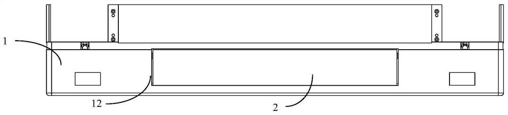
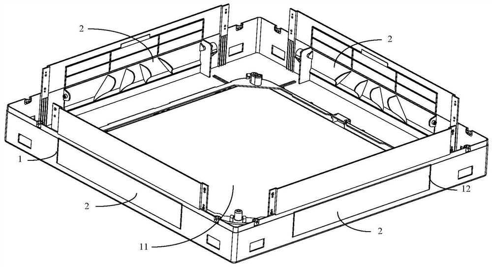
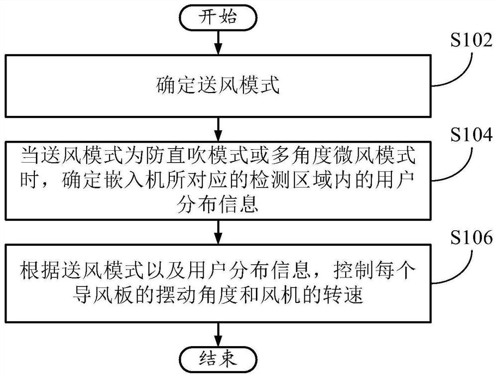
[0037] First refer to Figure 1 to Figure 7 , and describe the control method of the present invention in conjunction with the embedded machine. in, figure 1 It is a side view of the embedding machine of the present invention; figure 2 It is a schematic diagram of the embedding machine of the present invention; image 3 It is a schematic flow chart of the control method of the present invention; Figure 4It is a schematic flow chart of the control method of the present invention; Figure 5 It is a schematic diagram of the division of the detection area of ​​the present invention; Figure 6 It is a schematic diagram of the division of the detection area of ​​the present invention; Figure 7 It is a schematic diagram of the division of the detection area of ​​the present invention.

[0038] Such as figure 1 and figure 2 As shown, the present embodiment provides a control method for an embedding machine, the embedding machine has an air outlet panel 1, the bottom surfac...

Embodiment 2

[0110] This embodiment provides an embedded machine, which includes: a memory; a processor; and computer instructions, which are stored in the memory and configured to be executed by the processor to implement the control method in Embodiment 1.

[0111] In this embodiment, when the embedded machine is running, the processor executes computer instructions, so that the embedded machine executes the control method in Embodiment 1, thus having all the beneficial effects of Embodiment 1, such as adjusting the wind deflector according to the user's distribution The angle is convenient to improve the comfort of the user, etc.

Embodiment 3

[0113] This embodiment provides a computer-readable storage medium, where computer instructions are stored in the computer-readable storage medium, and the computer instructions are executed by a processor to implement the control method in Embodiment 1.

[0114] In this embodiment, when the computer instructions are executed by the processor, the embedded machine executes the control method in Embodiment 1, thus having all the beneficial effects of Embodiment 1, such as adjusting the angle of the wind deflector according to the distribution of the user, It is convenient to improve user comfort and the like.


PUM


Abstract

The invention relates to the technical field of air conditioners. The invention aims to solve the problem that an existing embedded machine cannot swing the air blowing angle of an air deflector in real time according to the positions of users. To achieve the purpose, the control method is used for an embedded machine, the embedded machine is provided with an air discharging panel, the bottom faceof the air discharging panel is provided with an air inlet, the side face of the air discharging panel is provided with a plurality of air outlets, an air deflector is arranged in each air outlet, and the air deflectors are connected with the air discharging panel in a pivoted mode. The control method comprises the following steps that 1, an air supply mode is determined; 2, when the air supply mode adopts a direct blowing prevention mode or a multi-angle breeze mode, user distribution information in a detection area corresponding to the embedded machine is determined; and 3, according to theair supply mode and the user distribution information, the swing angle of each air deflector and/or the rotating speed of a draught fan is controlled. According to the control method, the swing angleof each air deflector and the rotating speed of the draught fan are controlled according to the air supply mode and the user distribution information, the angles of the air deflectors are adjusted according to distribution of the users, and the comfort degree of the users is conveniently improved.

Description

technical field [0001] The invention relates to the technical field of air conditioners, in particular to a control method, a control system and an embedded machine. Background technique [0002] At present, embedded air conditioners are mostly used in large areas such as office buildings and shopping malls. However, traditional embedded air conditioners have problems such as a single air supply mode, and cannot swing the blowing angle of the air deflector in real time according to the user's position. [0003] Correspondingly, the field needs a new control method for embedded machines to solve the above problems. Contents of the invention [0004] In order to solve the above-mentioned problems in the prior art, that is, in order to solve the problem that the existing embedding machine cannot swing the blowing angle of the wind deflector in real time according to the position of the user, the present invention provides a control method, which is used in the embedding machi...

Claims


Application Information

Patent Timeline
Patent Type & Authority Applications(China)
IPC IPC(8): F24F1/0014F24F1/0047F24F11/64F24F11/65F24F11/77F24F11/79F24F11/88F24F11/89F24F13/14
CPCF24F1/0014F24F1/0047F24F11/64F24F11/65F24F11/77F24F11/79F24F11/88F24F11/89F24F13/1413Y02B30/70
Inventor 张继通张吉义董德智陈冬铃赵心蕾李珍王海梅刘新波
Owner QINGDAO HAIER AIR CONDITIONING ELECTRONICS CO LTD
Why Eureka
Try Eureka