
Inertia response power distribution method in wind power plant considering rotation speed constraint

A technology of inertia response and distribution method, applied in the field of inertia response power distribution in wind farms, can solve the problems of secondary frequency drop of wind turbine speed protection device, improper distribution of inertia response power of grid-connected wind turbines, etc., to avoid frequency secondary The effect of the drop problem

Pending Publication Date: 2021-11-16
YUNNAN POWER GRID CO LTD ELECTRIC POWER RES INST
View PDF4 Cites 3 Cited by
  • Summary
  • Abstract
  • Description
  • Claims
  • Application Information

AI Technical Summary

Problems solved by technology

[0004] This application provides a method of inertia response power distribution in wind farms considering speed constraints to solve the problem of secondary frequency drop caused by the operation of wind turbine speed protection devices caused by improper distribution of inertia response power of grid-connected wind turbines in wind farms

Method used


Image

  • Inertia response power distribution method in wind power plant considering rotation speed constraint
  • Inertia response power distribution method in wind power plant considering rotation speed constraint
  • Inertia response power distribution method in wind power plant considering rotation speed constraint

Examples


Embodiment Construction

[0044] The embodiments will be described in detail hereinafter, examples of which are illustrated in the accompanying drawings. When the following description refers to the accompanying drawings, the same numerals in different drawings refer to the same or similar elements unless otherwise indicated. The implementations described in the following examples do not represent all implementations consistent with this application. These are merely examples of systems and methods consistent with aspects of the present application as recited in the claims.

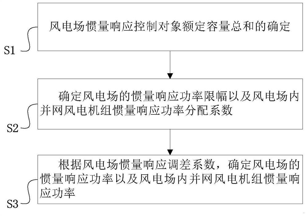
[0045] see figure 1 , is a schematic diagram of an inertia-response power allocation method in a wind farm considering rotational speed constraints provided by an embodiment of the present application.

[0046] The embodiment of the present application provides a method of inertia response power distribution in a wind farm considering speed constraints, including the following steps:

[0047] S1: Determination of the total rated ...


PUM


Abstract

The invention provides an inertia response power distribution method in a wind power plant considering rotation speed constraint, and the method comprises the following steps: determining a grid-connected wind turbine generator with inertia response capability in the wind power plant when active power shortage occurs; calculating the rated capacity sum of inertia response control objects of the wind power plant according to the grid-connected wind turbine generator; determining the short-time adjustable capacity and the short-time adjustable capacity of the grid-connected wind turbine generator in the wind power plant, the inertia response power upward adjustment amplitude limit and the inertia response power downward adjustment amplitude limit of the wind power plant and the inertia response power distribution coefficient of the grid-connected wind turbine generator in the wind power plant according to the rotating speed constraint and the current transformer capacity limiting condition; obtaining the inertia response power of the wind power plant and the inertia response power of the grid-connected wind turbine generators in the wind power plant according to the wind power plant inertia response difference adjustment coefficient and the sum of the rated capacity of the wind power plant inertia response control object, and transmitting an inertia response power instruction to the grid-connected wind turbine generators, so the grid-connected wind turbine generators are increased to achieve power support.

Description

technical field [0001] The present application relates to the technical field of wind turbine inertia response in-field control, in particular to an inertia response power distribution method in a wind farm considering speed constraints. Background technique [0002] When there is a shortage of active power in the grid, new energy units represented by wind power are affected by the maximum power point tracking control, so they can only provide power support to the system by releasing the kinetic energy of the rotor to increase its active output in a short period of time. Wind farm inertia response control is the most widely used control method for wind turbines to release rotor kinetic energy in actual engineering. This control method is based on the maximum power point tracking control of the wind farm active power control system. Differential proportional equivalence is achieved. [0003] However, the above-mentioned control method only solves the problem of how to make t...

Claims


Application Information

Patent Timeline
Patent Type & Authority Applications(China)
IPC IPC(8): H02J3/48H02J3/24H02J3/46H02J3/38
CPCH02J3/48H02J3/241H02J3/466H02J3/381H02J2300/28Y02E10/76
Inventor 何廷一李崇涛马红升吴水军沐润志和鹏
Owner YUNNAN POWER GRID CO LTD ELECTRIC POWER RES INST
Learn More