Crude oil treatment equipment for oil exploitation environment protection

A technology for environmental protection and oil extraction, which is applied in the directions of dehydration/demulsification by electricity/magnetism, dehydration/demulsification by chemical methods, etc. It can solve problems such as electrode plate corrosion, crude oil desalination work efficiency cannot be further improved, and crude oil content is large , to achieve the effect of improving work efficiency

Active Publication Date: 2021-11-19
东营昱辰技术有限公司
View PDF3 Cites 2 Cited by
  • Summary
  • Abstract
  • Description
  • Claims
  • Application Information

AI Technical Summary

Problems solved by technology

[0003] During the electrolytic desalination of crude oil, due to the need to keep stirring the crude oil, when the demulsifier is added, the demulsifier will be broken up by the high-speed rotating stirring rod, and part of the broken up demulsifier will easily fly to and adhere to the On the electrode plate, the electrode plate is corroded by the demulsifier, which affects the service life of the electrode plate. In addition, due to the large space in the electrolysis chamber, the proportion of the demulsifier and the water sprayed into the crude oil is very small. The distribution of emulsion and clear water is scattered, and they will not be able to effectively cooperate with each other to dilute impurities, so that the desalination efficiency of crude oil cannot be further improved
[0004] After the electrolytic desalination of crude oil is completed, after standing for a period of time, some impurities will enter the wastewater layer from the crude oil layer and deposit on the bottom of the water, and then open the drain valve to allow the wastewater to drive the impurities to flow out from the bilge and collect them. The remaining crude oil is collected. However, when the waste water is drained, in order to ensure that the suspended impurities in the clear water can be completely removed, the draining time of the clear water will be extended, especially when the clear water is discharged to the end, due to liquid flow. The vortex will cause a large amount of crude oil to be removed from the middle along with the wastewater, so that the discharged wastewater contains a large amount of crude oil, which will make the cleaning steps of the wastewater in the later stage heavy.

Method used


Image

  • Crude oil treatment equipment for oil exploitation environment protection
  • Crude oil treatment equipment for oil exploitation environment protection
  • Crude oil treatment equipment for oil exploitation environment protection

Examples


Embodiment 1

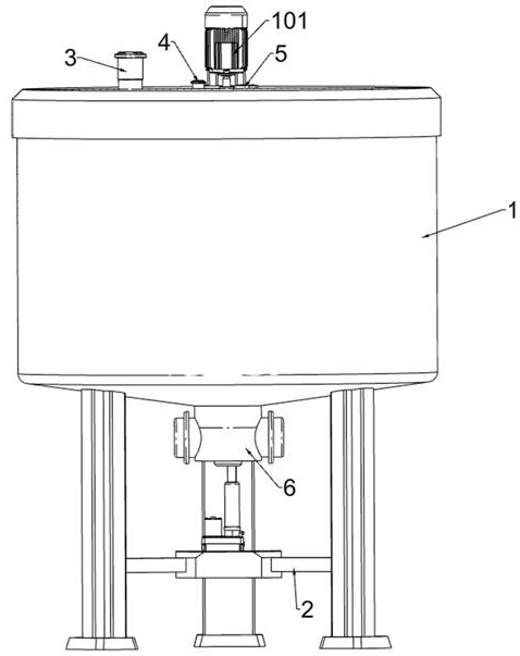
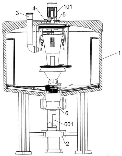
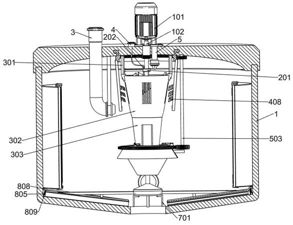
[0038] A kind of crude oil processing equipment for environmental protection of oil exploitation, such as Figure 1-Figure 4 As shown, it includes stirring assembly, milking and dilution assembly, central drainage assembly, auxiliary drainage assembly, cleaning assembly, bottom valve assembly, electrolysis chamber 1, fixing plate 2, oil delivery pipe 3, clean water pipe 4, demulsifier nozzle 5 and liquid outlet Pipe 6; the lower part of the electrolysis chamber 1 is fixedly connected with a fixed plate 2; the top plate of the electrolysis chamber 1 is connected with an oil delivery pipe 3; the top plate of the electrolysis chamber 1 is connected with a clean water pipe 4; The bottom plate of the electrolysis chamber 1 is connected with a liquid outlet pipe 6; the top plate of the electrolysis chamber 1 is connected with a stirring assembly; The top plate is bolted to the central drainage assembly; the left part of the whipping and dilution assembly is bolted to the central dra...

Embodiment 2

[0055] On the basis of Example 1, such as figure 2 and Figure 10-Figure 11 As shown, a rotating assembly is also included. The bottom plate of the electrolysis chamber 1 is provided with a rotating assembly. The rotating assembly includes a fourth fixed frame 701, a cover plate 702, a fifth spur gear 703, a sixth spur gear 704, and a third annular slide plate. 705 and the fourth gear ring 706; the bottom plate of the electrolysis cabin 1 is fixedly connected with the fourth fixing frame 701; the cover plate 702 is fixed on the upper surface of the third annular slide plate 705, and the internal parts are sealed to prevent corrosion. The lower end of the first rotating shaft 102 is rotationally connected with the fourth fixed frame 701; the lower end of the first rotating shaft 102 is fixedly connected with the fifth spur gear 703; the upper side of the fourth fixed frame 701 is connected with the sixth spur gear 704 through the rotating shaft; The spur gear 703 meshes with ...


PUM


Abstract

The invention relates to the technical field of oil treatment, in particular to crude oil treatment equipment for oil exploitation environment protection. The technical problems to be solved are that the demulsifier and clear water are distributed in a scattered mode, the desalting work efficiency of crude oil is affected, and the content of crude oil in waste water discharged in the later period is large due to the fact that impurities are distributed in a scattered mode. According to the technical scheme, the crude oil treatment equipment for oil exploitation environment protection comprises a stirring assembly, a milking and diluting assembly and the like; and a demulsifier nozzle is fixedly connected to a top plate of the electrolysis cabin. In the technical scheme provided by the invention, impurities in crude oil and clear water are intensively demulsified, and clear water is timely supplemented to dilute the impurities, so that the working efficiency of mutual cooperation of the demulsifier and the clear water is greatly improved, and most impurities are concentrated in the central area of the bottom of a cabin; and a large amount of crude oil can be prevented from being mixed in wastewater in later layered drainage work.

Description

technical field [0001] The invention relates to the technical field of petroleum processing, in particular to crude oil processing equipment for environmental protection of petroleum exploitation. Background technique [0002] The crude oil obtained after oil extraction needs to be desalted and dehydrated first, and then dewaxed and reformed to facilitate long-distance transportation. The desalted and dehydrated crude oil is usually treated by electrolysis, which means that the crude oil is introduced into the electrolysis chamber and a demulsifier is added. The desalted crude oil and water are separated and collected separately after electrolysis. [0003] During the electrolytic desalination of crude oil, due to the need to keep stirring the crude oil, when the demulsifier is added, the demulsifier will be broken up by the high-speed rotating stirring rod, and part of the broken up demulsifier will easily fly to and adhere to the On the electrode plate, the electrode plat...

Claims


Application Information

Patent Timeline
Patent Type & Authority Applications(China)
IPC IPC(8): C10G33/04C10G33/02
CPCC10G33/04C10G33/02
Inventor 陈文强
Owner 东营昱辰技术有限公司
Why Eureka
Try Eureka