
Metasurface optical element, design method and structured light projection module

A technology of optical components and design methods, applied in the optical field, can solve the problems of large space occupation and low alignment accuracy, and achieve the effect of reducing alignment errors and reducing space

Pending Publication Date: 2021-11-19
ZHEJIANG CRYSTAL OPTECH
View PDF13 Cites 5 Cited by
  • Summary
  • Abstract
  • Description
  • Claims
  • Application Information

AI Technical Summary

Problems solved by technology

[0004] The purpose of this application is to provide a meta-surface optical element and design method, and a structured light projection module to improve the existing structured light projection module that takes up a lot of space and has low alignment accuracy. low problem

Method used


Image

  • Metasurface optical element, design method and structured light projection module
  • Metasurface optical element, design method and structured light projection module
  • Metasurface optical element, design method and structured light projection module

Examples


Embodiment Construction

[0042] In order to make the purposes, technical solutions and advantages of the embodiments of the present application clearer, the technical solutions in the embodiments of the present application will be clearly and completely described below in conjunction with the drawings in the embodiments of the present application. Obviously, the described embodiments It is a part of the embodiments of this application, not all of them. The components of the embodiments of the application generally described and illustrated in the figures herein may be arranged and designed in a variety of different configurations.

[0043] Accordingly, the following detailed description of the embodiments of the application provided in the accompanying drawings is not intended to limit the scope of the claimed application, but merely represents selected embodiments of the application. It should be noted that, in the case of no conflict, various features in the embodiments of the present application ma...


PUM

PropertyMeasurementUnit
lengthaaaaaaaaaa
diameteraaaaaaaaaa
heightaaaaaaaaaa

Abstract

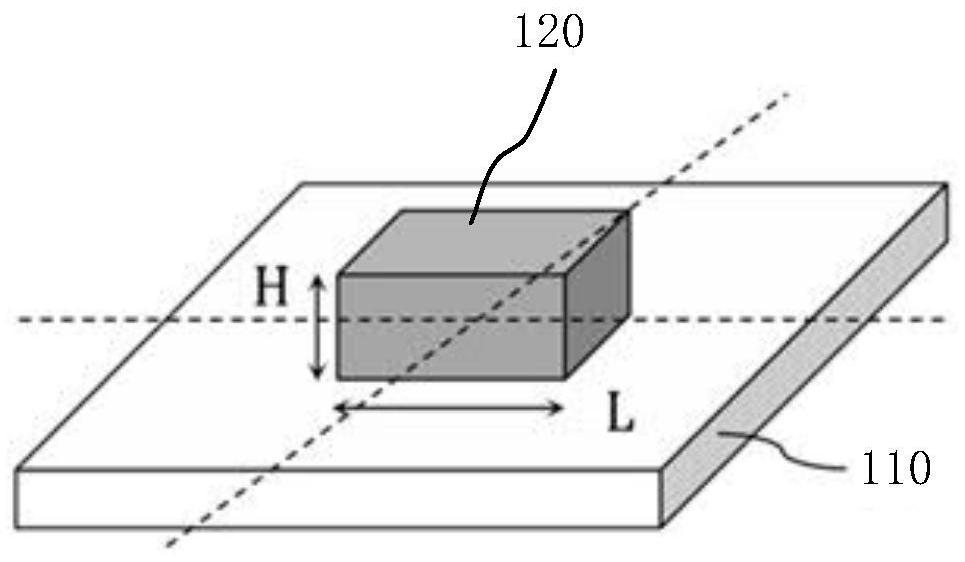
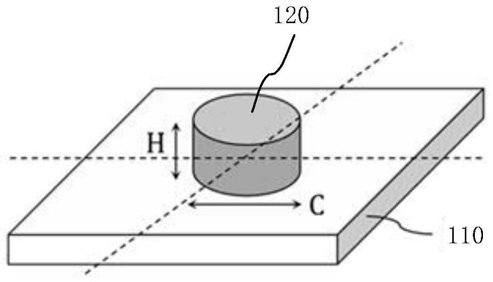
The invention provides a metasurface optical element, a design method and a structured light projection module, and relates to the technical field of optics. The metasurface optical element comprises a substrate and a plurality of nanometer antennas which are arranged on the substrate and modulate incident beams through transmission phases, at least two nanometer antennas are different in size, the nanometer antennas are distributed on the substrate in an array mode, the distance between the centers of every two adjacent nanometer antennas is the same, and the transmission phase of each nanometer antenna is the superposition of a collimation phase and a diffraction phase. Therefore, the formed metasurface optical element can have collimation and diffraction functions at the same time, that is, a collimation element and a diffraction element are integrated, the space occupied by the existing two independent optical elements for collimation and diffraction is effectively reduced, and meanwhile, due to the fact that alignment assembly of the collimation element and the diffraction element is omitted, the alignment error caused by the alignment assembly can be effectively reduced.

Description

technical field [0001] The present application relates to the field of optical technology, in particular, to a metasurface optical element, a design method, and a structured light projection module. Background technique [0002] Structured light projects a specific pattern onto the surface of an object, collects it through the receiving module, calculates the position and depth information of the object according to the change of the light signal caused by the object, and then restores the entire depth space. The pattern can be designed as stripes, regular lattices, grids, speckles, codes, etc., or even more complex light shapes. With the development of optical technology, the application range of structured light is more and more extensive, such as face recognition, gesture recognition, projector, three-dimensional (Three-dimensional, 3D) outline reconstruction, depth measurement, anti-counterfeiting identification, etc. Therefore, how to provide a projection module that s...

Claims


Application Information

Patent Timeline
Patent Type & Authority Applications(China)
IPC IPC(8): G02B5/18G02B27/00G02B27/30G02B27/42
CPCG02B5/1809G02B5/1866G02B27/0012G02B27/30G02B27/4205G02B2005/1804
Inventor 汪肇坤伍未名刘风雷
Owner ZHEJIANG CRYSTAL OPTECH
Learn More