
Clamping and feeding mechanism capable of moving in four directions and used for gear box machining

A gear box and square technology, applied in the direction of workpiece clamping devices, workbenches, manufacturing tools, etc., can solve problems such as inability to adjust, machine damage, singleness, etc., and achieve the effect of preventing the spread of sewage and improving the degree of cleanliness

Active Publication Date: 2021-11-23
无锡瑞圣机械科技有限公司
View PDF5 Cites 0 Cited by
  • Summary
  • Abstract
  • Description
  • Claims
  • Application Information

AI Technical Summary

Problems solved by technology

[0003] When the existing feeding mechanism is in use, after fixing the gear box shell, a separate steering mechanism is usually used to adjust the angle of the gear box shell, so that It is relatively single, and it is impossible to adjust the distance between the X-axis and the Y-axis where the gearbox is located, resulting in inconvenient loading. At the same time, when the gear box shell is polished and turned, it lacks the guidance of the cleaning sewage generated. Due to the structure of the flow, the sewage can infiltrate randomly, which is easy to cause damage to the machine. Therefore, we need to propose a clamping and feeding mechanism that can move in all directions for gearbox processing.

Method used


Image

  • Clamping and feeding mechanism capable of moving in four directions and used for gear box machining
  • Clamping and feeding mechanism capable of moving in four directions and used for gear box machining
  • Clamping and feeding mechanism capable of moving in four directions and used for gear box machining

Examples


Embodiment 1

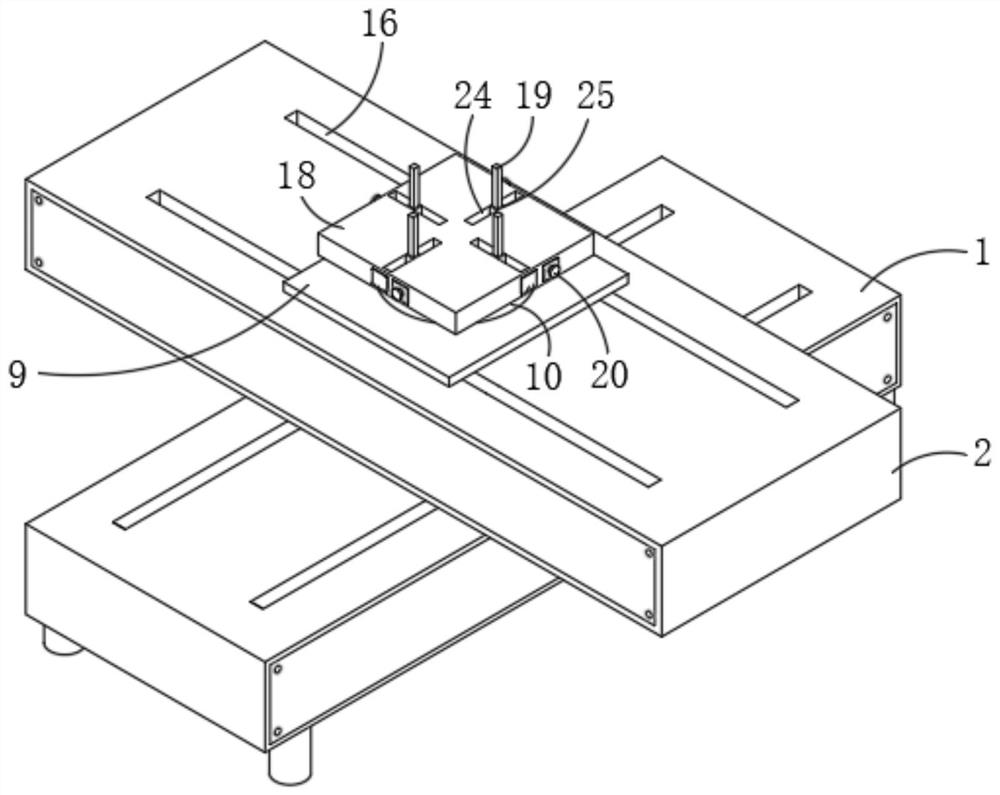
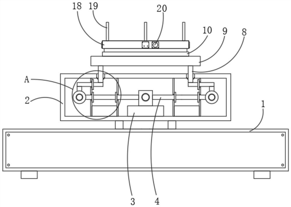
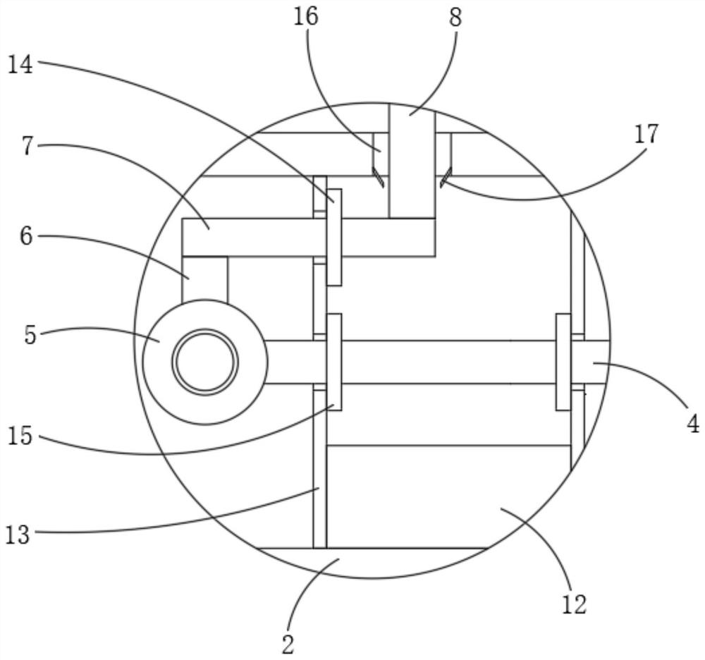
[0027] see Figure 1-3 , the present invention provides a technical solution: a four-way movable clamping and feeding mechanism for gear box processing, including a first shell 1 and a second shell 2, the first shell 1 and the second shell The inside of 2 is fixedly equipped with electric slide table 3, and both sides of the transmission end of electric slide table 3 are all fixedly installed with transmission rod 4, and the two ends of transmission rod 4 are all provided with ball screw 5 and are connected with the transmission end of ball screw 5. Rotationally connected, both ends of the ball screw 5 are bolted to the inner walls of the first housing 1 and the second housing 2 . By starting the electric sliding table 3, the transmission end of the electric sliding table 3 drives the transmission rod 4 to move, the transmission rod 4 drives the moving end of the ball screw 5 to move, and the moving end of the ball screw 5 drives the first connecting rod 6 and the second conne...

Embodiment 2

[0031] see figure 2 and image 3 , the difference between this embodiment 2 and embodiment 1 is:

[0032] The inner cavities of the first housing 1 and the second housing 2 are slidably connected with the collection box 12 between the ball screw 5 and the electric slide table 3, and the surface of the transmission rod 4 is located on both sides of the collection box 12. A baffle 13 is sleeved, and the inner side of the baffle 13 is slidably attached to the surface of the collection box 12 , and the top of the baffle 13 is respectively attached to the surfaces of the first casing 1 and the second casing 2 . By setting the baffle plate 13, the baffle plate 13 is used to cover both sides of the third through groove 16, to block the sewage entering through the third through groove 16, to prevent the sewage from spreading, and to affect the ball screw 5 and the electric slide table 3.

[0033] The top of the second housing 2 is provided with a third through groove 16 compatible...

Embodiment 3

[0038] see figure 1 , Figure 4 and Figure 5 , the difference between this embodiment 3 and embodiment 1 and embodiment 2 is:

[0039] The clamping mechanism 11 includes a plate body 18, and clamping rods 19 are slidably installed around the top of the plate body 18, and screw rods 20 are threaded around the plate body 18, and one end of the screw rod 20 extends to the inside of the plate body 18 and is threaded on the surface. Connected with a screw sleeve 21 , the side of the screw sleeve 21 close to the clamping rod 19 is fixedly mounted with a slanting rod 22 , and one end of the slanting rod 22 is connected to the clamping rod 19 in transmission. The inner cavity of the second chute 24 is provided with a connecting block 25, the top of the connecting block 25 is welded to the bottom of the clamping bar 19, and one end of the oblique bar 22 extends to the inner cavity of the second chute 24 and is welded to one side of the connecting block 25 .

[0040] The inside of ...


PUM


Abstract

The invention discloses a clamping and feeding mechanism capable of moving in four directions and used for gear box machining. The clamping and feeding mechanism comprises a first shell and a second shell, electric sliding tables are fixedly mounted in the first shell and the second shell correspondingly, and transmission rods are fixedly mounted at the two sides of the transmission ends of the electric sliding tables correspondingly; and ball screws are arranged at the two ends of the transmission rods, and the transmission rods are rotationally connected with the transmission ends of the ball screws. According to the clamping and feeding mechanism, by arranging a baffle, a collecting box, a first waterproof ring and a second waterproof ring, sewage entering the second shell is drained and collected, so that the purpose of preventing sewage from spreading is achieved, and the cleanliness of the device is improved; the clamping and feeding mechanism has the advantages that multi-angle moving adjustment can be achieved, and sewage drainage is facilitated; and inclined rods are arranged in a clamping mechanism, the situation that transmission between a screw and a screw sleeve is blocked due to the fact that the screw is polluted by sewage can be prevented while the transmission effect is achieved, and meanwhile, the sewage can be discharged in time by forming drainage holes.

Description

technical field [0001] The invention relates to the technical field of gear box processing equipment, in particular to a four-way movable clamping and feeding mechanism for gear box processing. Background technique [0002] The gearbox has a wide range of applications, such as the application in wind turbines. The gearbox is an important mechanical component widely used in wind turbines. Its main function is to transmit the power generated by the wind wheel under the action of the wind to the Generator and make it get the corresponding speed. Usually the speed of the wind wheel is very low, far from the speed required by the generator for power generation. It must be realized by the speed-up effect of the gear pair of the gearbox, so the gearbox is also called As a speed-up gearbox, the gear box needs to use a feeding mechanism during production and processing. [0003] When the existing feeding mechanism is in use, after the gearbox casing is fixed, a separate steering mec...

Claims


Application Information

Patent Timeline
Patent Type & Authority Applications(China)
IPC IPC(8): B25B11/00B25H1/00B25H1/10
CPCB25B11/00B25H1/10B25H1/00Y02E10/72
Inventor 李晓将刘兴兴蒲令赵岩
Owner 无锡瑞圣机械科技有限公司
Learn More