Novel supporting device for building construction and building construction method thereof

A technology of building construction and supporting devices, which is applied in the direction of construction, building structure, and on-site preparation of building components, which can solve the problems of cumbersome steps, low construction efficiency, and complexity, and achieve the effect of large supporting area and good supporting effect

Pending Publication Date: 2021-11-23
91340100149147289C
View PDF5 Cites 0 Cited by
  • Summary
  • Abstract
  • Description
  • Claims
  • Application Information

AI Technical Summary

Problems solved by technology

[0003] During the construction, it is necessary to support the building formwork, etc. When the existing support device is in construction, the steps are cumbersome and complicated, and the construction efficiency is low, and the existing support device is difficult to simultaneously support the horizontal support surface and the vertical surface at the same time. Support, for this reason, the present invention proposes a kind of novel building construction support device and its building construction method that can solve the above problems

Method used


Image

  • Novel supporting device for building construction and building construction method thereof
  • Novel supporting device for building construction and building construction method thereof
  • Novel supporting device for building construction and building construction method thereof

Examples


Embodiment 1

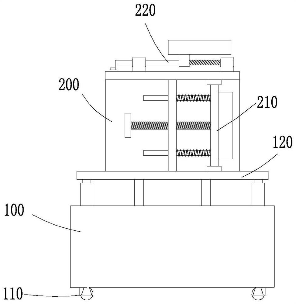
[0036] The present invention provides a technical solution: a novel supporting device for building construction, comprising:

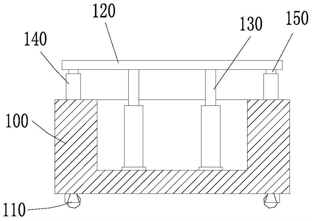
[0037] The fixed seat 100, the upper end of the fixed seat 100 is provided with a tank body, a hydraulic cylinder group 130 is installed in the tank body, and the piston rod of the hydraulic cylinder group 130 is connected with an adjustment plate 120;

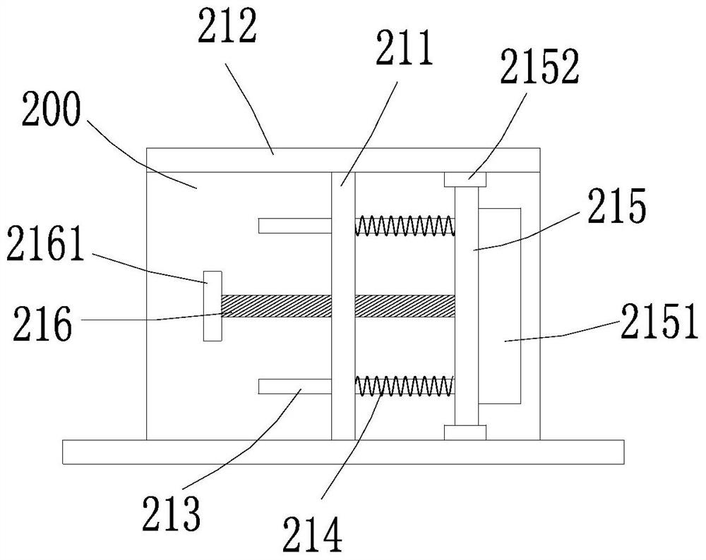
[0038] Support frame 200, the support frame 200 is arranged on the upper end of the adjustment plate 120, the top of the support frame 200 is provided with a horizontal support assembly 220 for supporting the horizontal support surface, and one side of the support frame 200 is provided with a vertical support assembly 210 for supporting the vertical Supporting surface; the vertical support assembly 210 includes a vertical plate 211 arranged inside the support frame 200, and a horizontal plate 212 on the top of the support frame plate, the vertical plate 211 is movably worn with several groups of movable...

Embodiment 2

[0041] On the basis of Embodiment 1, four corners of the upper end of the fixing base 100 are provided with cylinders 140 , and each set of cylinders 140 is pierced with a limiting column 150 , which extends vertically upwards and is connected with the adjusting plate 120 . The fixed seat 100 is equipped with a moving wheel 110, and the moving wheel 110 is a self-locking wheel. The upper end and the lower end of the moving plate 215 are respectively provided with sliders 2152, and the adjustment plate 120 and the horizontal plate 212 are respectively provided with chute, and the slider 2152 is movably engaged with the chute.

[0042] Specifically, when the hydraulic cylinder group 130 drives the adjustment plate 120 to move vertically, the limit post 150 moves along the cylinder body 140, so that the adjustment plate 120 always maintains a stable and balanced state when adjusting the height, and the moving plate 215 moves between the adjustment plate 120 and the horizontal posi...

Embodiment 3

[0044] On the basis of Embodiment 1 or Embodiment 2, the horizontal support assembly 220 includes a first fixed block 221 and a second fixed block 222 arranged at intervals on the upper end of the horizontal plate 212, and the first fixed block 221 and the second fixed block 222 are respectively installed There is a bearing assembly, and a rotating rod 223 is pierced between the two groups of bearing assemblies. The rotating rod 223 is provided with a threaded section 2231, and the threaded section 2231 is screwed with a first moving block 224, and the upper end of the first moving block 224 is provided with a middle horizontal abutment The plate 2241 , one end of the rotating rod 223 passes through the first fixing block 221 and is connected with the second rotating handle 2232 . The first block is provided with slide bars 225 on both sides of the rotating rod 223, and the second moving block 226 is slidably sleeved on the sliding bar 225. The upper end of the second moving bl...


PUM


Abstract

The invention discloses a novel supporting device for building construction. The novel supporting device comprises a fixing seat and a supporting frame, wherein a groove body is formed in the upper end of the fixing seat, a hydraulic cylinder set is installed in the groove body, and a piston rod of the hydraulic cylinder set is connected with an adjusting plate; the supporting frame is arranged at the upper end of the adjusting plate, a horizontal supporting assembly is arranged at the top of the supporting frame and used for supporting a horizontal supporting surface, and a vertical supporting assembly is arranged on one side of the supporting frame and used for supporting a vertical supporting surface; and the vertical supporting assembly comprises a vertical plate arranged in the supporting frame and a transverse plate horizontally arranged at the upper end of a supporting frame plate, a plurality of sets of movable rods are movably arranged on the vertical plate in a penetrating mode, springs are wound on the movable rods, one of the ends of the movable rods is connected with a movable plate, a vertical abutting plate is arranged on the front side of the movable plate, a screw rod is connected to the middle of the vertical plate in a threaded mode, a first rotating handle is arranged at one end of the screw rod, and the other end of the screw rod makes contact with the vertical abutting plate. The novel supporting device is good in supporting effect, high in stability, simple in construction step and high in construction efficiency.

Description

technical field [0001] The invention relates to the technical field of building construction, in particular to a novel supporting device for building construction and a building construction method thereof. Background technique [0002] At present, the construction industry is one of the important pillar industries of the national economy. It has a close relationship with the development of the entire country's economy and the improvement of people's lives. Driven by the continuous increase in infrastructure construction and urbanization, my country's construction industry maintains It has maintained a good growth momentum, and its economic benefits have continued to improve, making a greater contribution to the growth of the national economy. [0003] During the implementation of the building, it is necessary to support the building formwork, etc. When the existing supporting device is in construction, the steps are cumbersome and complicated, and the construction efficiency...

Claims


Application Information

Patent Timeline
Patent Type & Authority Applications(China)
IPC IPC(8): E04G25/04E04G25/06
CPCE04G25/04E04G25/06E04G2025/047
Inventor 周振铎郑全伟徐如涛
Owner 91340100149147289C
Why Eureka
Try Eureka