A position-adjustable handle rod and steering handle of agricultural machinery

A technology for steering handles and agricultural machinery, which is applied to the steering control and handlebars installed on the vehicle. It can solve the problems that the position of the handle bar cannot be adjusted, cannot meet the driver's manipulation needs, and misuse, etc., so as to achieve convenient one-handed operation. Effect

Active Publication Date: 2020-04-03
LOVOL HEAVY IND CO LTD
View PDF8 Cites 0 Cited by
  • Summary
  • Abstract
  • Description
  • Claims
  • Application Information

AI Technical Summary

Problems solved by technology

[0003] The technical problem to be solved by the present invention is that the position of the handle bar on the control panel of the agricultural motor vehicle cab cannot be adjusted at present, which cannot meet the driver's manipulation requirements for different positions, and it is easy to collide when entering and exiting the cab aisle, resulting in misoperation, etc.

Method used


Image

  • A position-adjustable handle rod and steering handle of agricultural machinery
  • A position-adjustable handle rod and steering handle of agricultural machinery
  • A position-adjustable handle rod and steering handle of agricultural machinery

Examples


Embodiment 1

[0049] figure 1 and figure 2It is a structural schematic diagram of a handle bar of an existing agricultural motor vehicle, which can realize front, rear, left, and right direction manipulation.

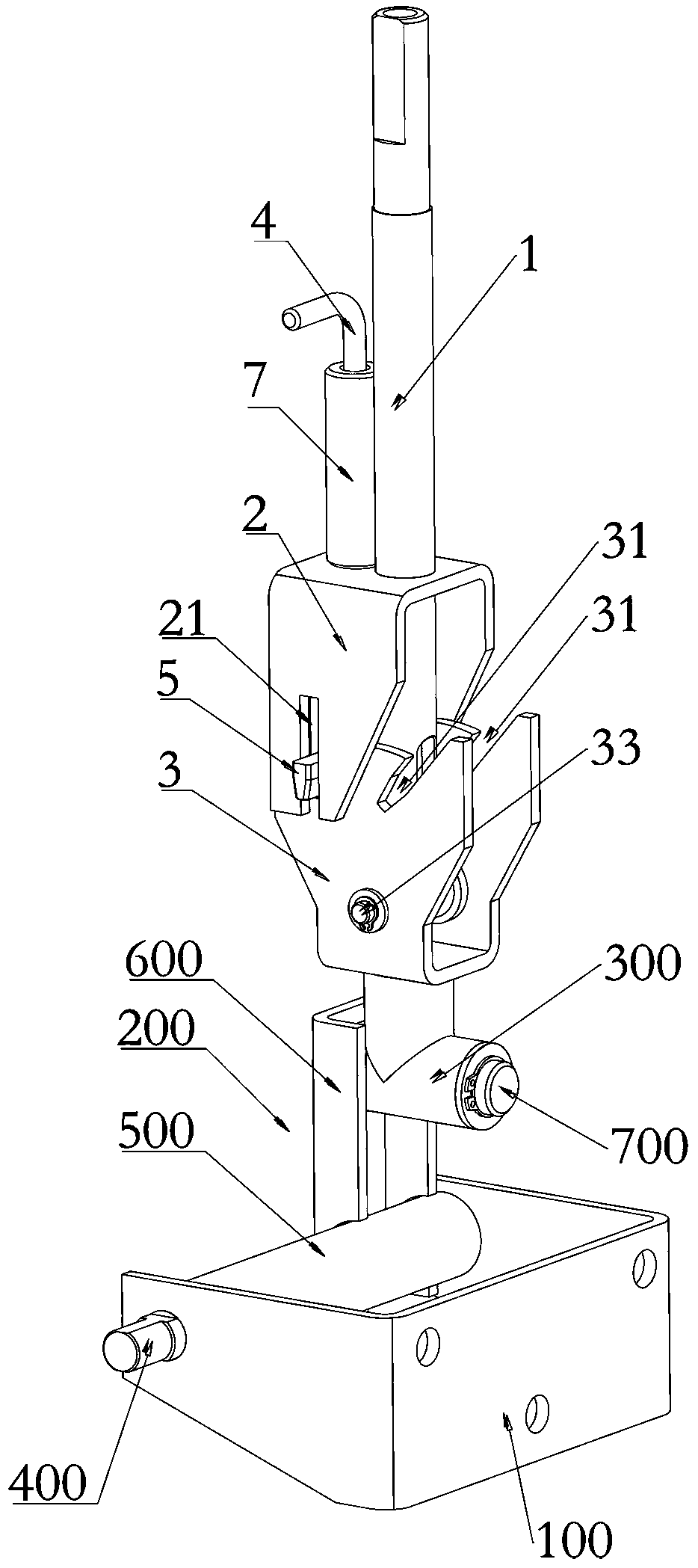
[0050] Such as Figure 3-Figure 12 As shown, a position-adjustable handle rod of this embodiment includes a handle rod welded 1, a limit bracket 2, a rotating support 3, a pull rod 4 and a limit pin 5, and the lower end of the handle rod welded 1 is hinged On the rotating support 3, the limit bracket 2 is fixed on the middle part of the handle rod welding 1, the limit bracket 2 is provided with a guide groove 21, and the pull rod 4 is movably arranged in the limit position. On the bracket 2 and arranged side by side with the handle bar welded 1, the lower end of the pull rod 4 is provided with a limit pin 5, and the limit pin 5 is elastically connected to the limit bracket 2 and is located in the guide groove 21 ; The rotating support 3 is provided with a number of limit grooves ...

Embodiment 2

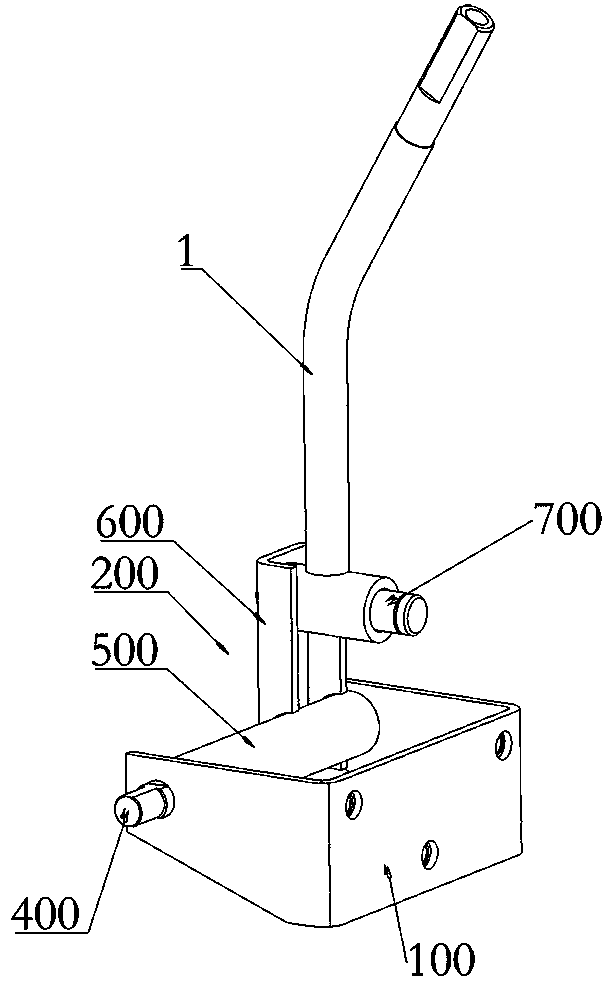
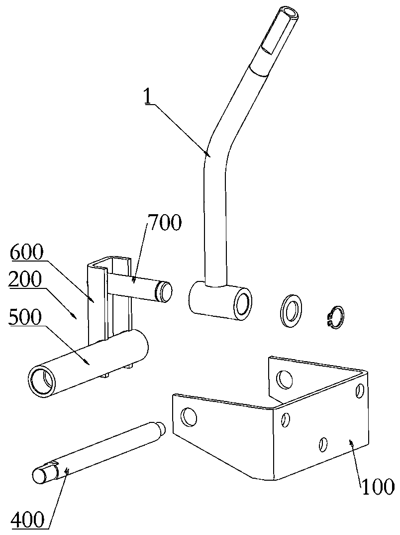
[0069] Such as Figure 3-Figure 12 As shown, a steering handle for agricultural machinery in this embodiment includes a fixed seat 100, a rotating seat welded 200 and the handle rod, and the bottom of the rotating support 3 is installed with a welded 1 vertically arranged with the handle rod. The second shaft sleeve 300; the first shaft 400 is installed on the fixed seat 100; the rotation seat welding 200 includes a third shaft sleeve 500, a connecting rod 600 and a second shaft 700, and the third shaft sleeve 500 and the second rotating shaft 700 are vertically connected to the connecting rod 600 respectively, the third bushing 500 and the second rotating shaft 700 are mutually misaligned and arranged vertically; the second bushing 300 is sleeved on the On the second rotating shaft 700 , the third sleeve 500 is sleeved on the first rotating shaft 400 .

[0070] The steering handle of this embodiment can switch between different operating angles according to the needs of the ...


PUM


Abstract

The invention relates to a position adjustable handle lever and an agricultural machinery steering handle. The position adjustable handle lever comprises a handle lever seaming, a limiting bracket, arotary support, a pull rod and a limiting pin, wherein the lower end of the handle lever seaming is hinged to the rotary support; the limiting bracket is fixed in the middle of the handle lever seaming; a guiding groove is formed in the limiting bracket; the pull rod is movably arranged on the limiting bracket; the pull rod and the handle lever seaming are arranged side by side; the limiting pin is arranged at the lower end of the pull rod, is in elastic connection onto the limiting bracket and is positioned in the guiding groove; a plurality of limiting grooves are sequentially formed in therotary support side by side; the limiting bracket is partially coincided with the rotary support, so that the guiding groove can be partially coincided with any of limiting grooves when the handle lever seaming rotates relative to the rotary support, wherein when the handle lever has position switching, the pull rod is pulled to move the limiting pin out of one limiting groove; the handle lever seaming is rotated to another position, so that the guiding groove is corresponding to another limiting groove, and the limiting pin is released and enters another limiting groove.

Description

technical field [0001] The invention relates to the related technical field of agricultural motor vehicles, in particular to a position-adjustable handle bar and an agricultural machinery steering handle. Background technique [0002] At present, the steering and lifting handles of the cab models of agricultural vehicles (such as crawler vehicles) on the market are located on the right console of the cab, and the angle of the joystick lever is fixed, which cannot meet the needs of different groups of people for the comfort of the joystick position. After the assembly of the control assembly is completed, the handle is bent beyond the console, and it is easy to touch it when the driver enters and exits the aisle of the cab, resulting in misoperation and potential safety hazards. Contents of the invention [0003] The technical problem to be solved by the present invention is that the position of the handle bar on the console of the agricultural motor vehicle cab cannot be a...

Claims


Application Information

Patent Timeline
Patent Type & Authority Patents(China)
IPC IPC(8): B62D1/12
CPCB62D1/12
Inventor 何松赵凯凯张桂健韩利剑倪树秀张国栋
Owner LOVOL HEAVY IND CO LTD
Why Eureka
Try Eureka