Position adjustable handle lever and agricultural machinery steering handle
A handle rod and lever technology, which is applied to steering control, handlebars and other directions installed on the car, can solve the problems of unadjustable position of the handle rod, unable to meet the driver's manipulation needs, misoperation, etc., and achieves a convenient one-handed operation. Effect
- Summary
- Abstract
- Description
- Claims
- Application Information
AI Technical Summary
Problems solved by technology
Method used
Image

Examples
Embodiment 1
[0049] figure 1 with figure 2 It is a schematic diagram of the structure of the handle bar of an existing agricultural motor vehicle, which can be manipulated in the front, back, left, and right directions.
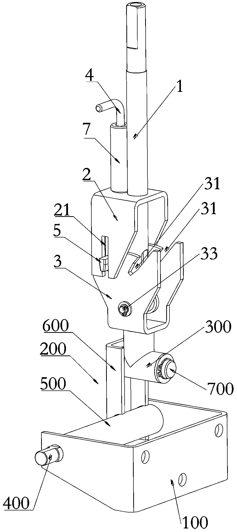
[0050] Such as Figure 3-Figure 12 As shown, a position-adjustable handle rod of this embodiment includes a handle rod welded 1, a limit bracket 2, a rotating support 3, a pull rod 4, and a limit pin 5. The handle rod is welded 1 and the lower end is hinged. On the rotating support 3, the limit bracket 2 is fixed in the middle of the handle bar welding 1, the limit bracket 2 is provided with a guide groove 21, and the pull rod 4 is movably arranged at the limit position. Arranged side by side on the bracket 2 and welded with the handle rod 1, a limit pin 5 is provided at the lower end of the pull rod 4, and the limit pin 5 is elastically connected to the limit bracket 2 and is located in the guide groove 21 The rotation support 3 is provided with a number of limit slots 31 ...
Embodiment 2
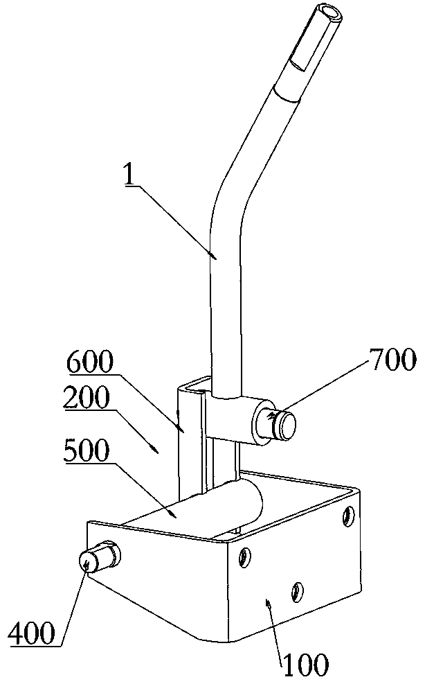
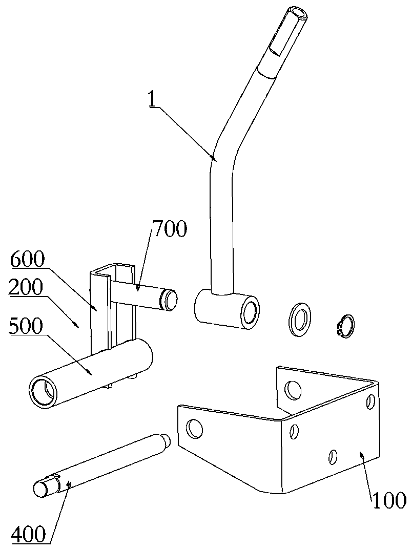
[0069] Such as Figure 3-Figure 12 As shown, an agricultural machinery steering handle of this embodiment includes a fixed seat 100, a rotating seat welding 200, and the handle rod. The bottom of the rotating support 3 is installed with the handle rod welding 1 perpendicularly arranged The second shaft sleeve 300; the fixed seat 100 is installed with a first rotating shaft 400; the rotating seat welding 200 includes a third shaft sleeve 500, a connecting rod 600 and a second rotating shaft 700, the third shaft sleeve 500 The second shaft 700 and the second shaft 700 are respectively connected to the connecting rod 600 vertically, the third shaft sleeve 500 and the second shaft 700 are misaligned and arranged vertically; the second shaft sleeve 300 is sleeved on the On the second rotating shaft 700, the third shaft sleeve 500 is sleeved on the first rotating shaft 400.
[0070] The steering handle of this embodiment can switch between different operating angles according to the ne...
PUM
 Abstract
Description
Claims
Application Information
 - R&D Engineer
- R&D Manager
- IP Professional
- Industry Leading Data Capabilities
- Powerful AI technology
- Patent DNA Extraction
Browse by: Latest US Patents, China's latest patents, Technical Efficacy Thesaurus, Application Domain, Technology Topic.
© 2024 PatSnap. All rights reserved.Legal|Privacy policy|Modern Slavery Act Transparency Statement|Sitemap