Image marking method and system

An image labeling and image technology, applied in the field of deep learning, can solve the problems of poor image labeling effect and low efficiency, and achieve the effect of improving labeling speed and labeling accuracy.

Pending Publication Date: 2021-11-26
北京理工大学重庆创新中心 +1
View PDF0 Cites 0 Cited by
  • Summary
  • Abstract
  • Description
  • Claims
  • Application Information

AI Technical Summary

Problems solved by technology

[0003] An image tagging method and system provided by the present invention mainly solves the technical problem of: the existing image tagging effect is not good and the efficiency is low

Method used


Image

  • Image marking method and system
  • Image marking method and system
  • Image marking method and system

Examples


Embodiment 1

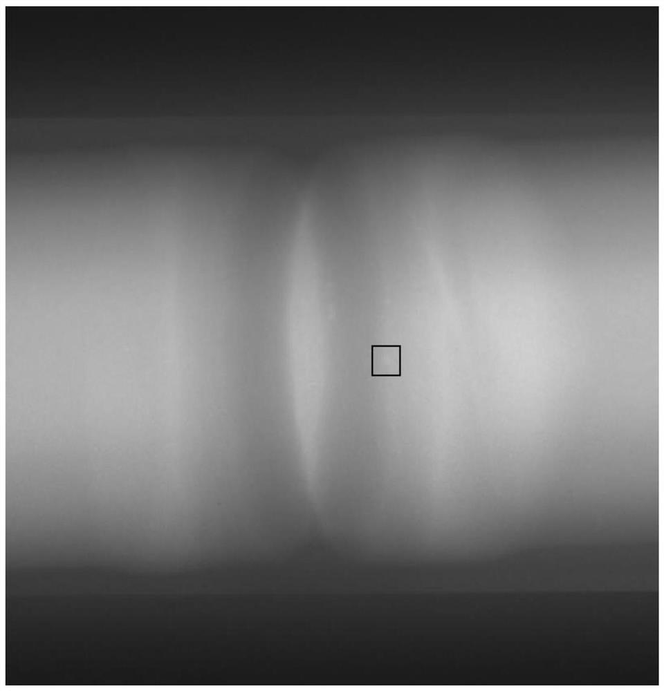
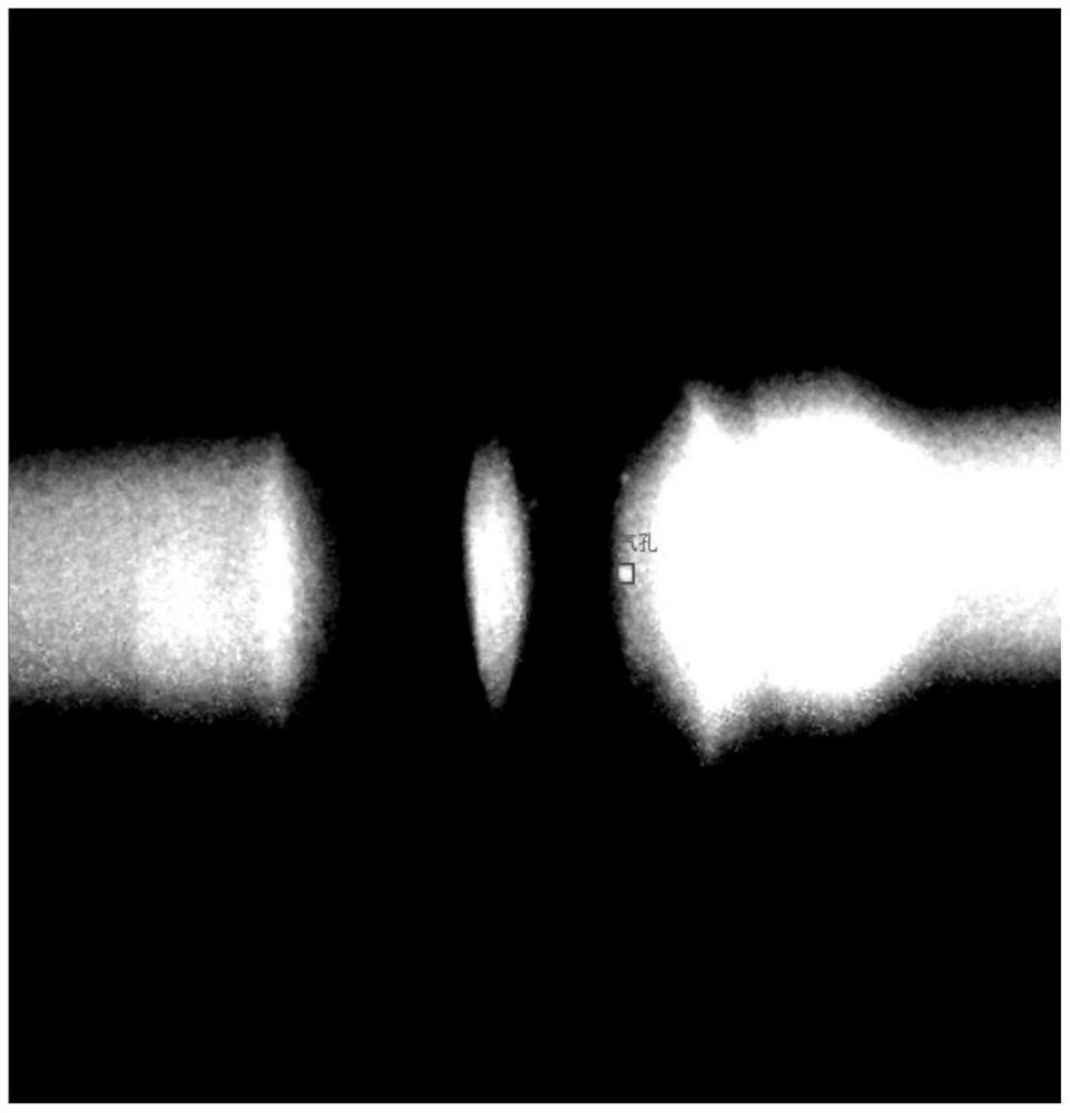
[0035] Such as figure 1 The radiographic image (black and white) of the weld seam is shown, and the object to be marked is the air hole (marked by a black frame). The contrast between the air hole and the background is not obvious, and effective marking cannot be performed. This solution provides an image annotation method, which greatly highlights the object to be annotated through local contrast adjustment. The annotated image is as follows: figure 2 As shown, the stomatal image can be clearly highlighted and the labeling accuracy is improved.

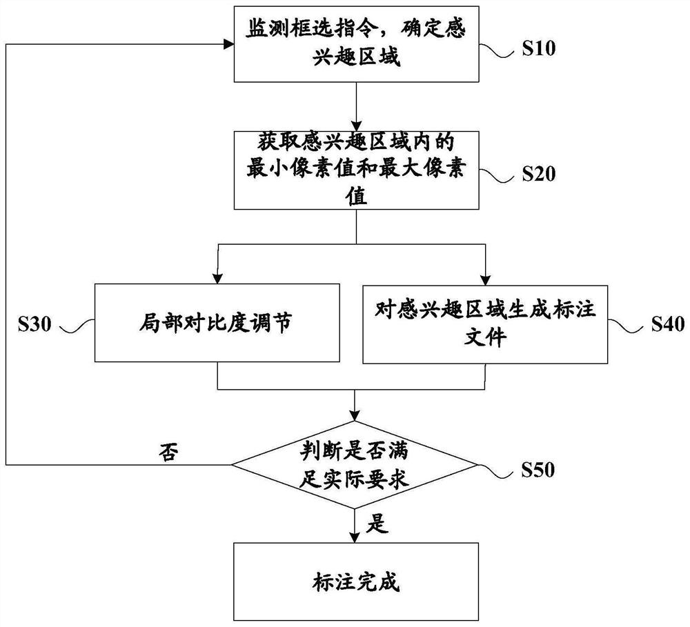
[0036] See image 3 , this program mainly includes the following steps:

[0037] S10. Monitoring the frame selection instruction to determine the region of interest;

[0038] S20. Obtain the minimum pixel value and the maximum pixel value in the region of interest;

[0039] S30, local contrast adjustment;

[0040] S40. Generate an annotation file for the region of interest;

[0041] S50, judging whether the actual requirements...

Embodiment 2

[0051] The above embodiments specifically process black and white images. On the basis of the above embodiments, this embodiment provides an image labeling method for processing color images, such as Figure 4 Shown is a multi-channel color traffic image, the object to be marked is a car (marked in a black box), the contrast between the car and the background is not obvious, and the color of the car cannot be seen clearly. This solution greatly highlights the object to be marked through local contrast adjustment, the color of the car is clearly visible, and the marking accuracy is improved. The marked image is as follows Figure 5 shown.

[0052] see Figure 4-5 , determine the minimum pixel value Rmin=149, Gmin=148, Bmin=146 and maximum pixel value Rmax=175, Gmax=173, Bmax=185 of each channel in the rectangular box, and then the R channel pixels of each pixel point in the whole picture The value is compared with 149 and 175. If it is less than or equal to 149, it is set to ...

Embodiment 3

[0055] On the basis of the first and second embodiments above, this embodiment provides an image tagging system to implement the steps of the image tagging method described in the first or second embodiment above, please refer to Figure 6 , the system consists of:

[0056] A monitoring module 61, configured to monitor the frame selection instruction of the image to be marked, so as to determine the region of interest;

[0057] An acquisition module 62, configured to acquire the minimum pixel value and the maximum pixel value in the region of interest;

[0058] The contrast adjustment module 63 is used to compare the pixel value of each pixel point in the set area with the minimum pixel value min and the maximum pixel value max, and set its pixel value to 0 if it is less than or equal to the minimum pixel value min; For a pixel equal to the maximum pixel value max, set its pixel value to 2 n -1, n is the bit depth of a single channel; for pixels between the minimum pixel val...


PUM


Abstract

The invention provides an image marking method and system, and the method comprises the steps: monitoring a frame selection instruction of a to-be-annotated image, so as to determine a region of interest; obtaining a minimum pixel value and a maximum pixel value in the region of interest; comparing the pixel value of each pixel point in the set area with the minimum pixel value min and the maximum pixel value max, and setting the pixel value of the pixel point smaller than or equal to the minimum pixel value min as 0; setting the pixel value of the pixel point of which the pixel value is greater than or equal to the maximum pixel value max as 2n-1; setting the pixel value of the pixel point between the minimum pixel value min and the maximum pixel value max to be (value-min) / (max-min) * (2n-1); and generating an annotation file by taking the region of interest as an annotation box. The pixel value of each channel of the region of interest can be expanded to the maximum range through local contrast adjustment, the to-be-labeled object is highlighted to the maximum extent, and the labeling precision is improved; contrast adjusting and marking are carried out at the same time, compared with an existing method of firstly adjusting the contrast and then marking, the contrast adjusting and marking method has the advantages that two steps are shortened into one step, and the marking speed can be increased.

Description

technical field [0001] The present invention relates to the technical field of deep learning, in particular to an image labeling method and system. Background technique [0002] The purpose of image annotation is to obtain a large number of labeled images, which constitute the training set of supervised deep learning, so image annotation is an indispensable basic work for deep learning. The current image annotation methods can be divided into two categories: one is image annotation without contrast adjustment, which will consume a lot of time to find objects to be annotated and is easy to miss for unobvious objects to be annotated; the other is with global contrast Adjusted image annotation, for the unobvious object to be annotated, that is, the local region of interest, the method has limited adjustment ability, the adjustment effect is not good, and adding a contrast adjustment step will consume more time. To sum up, the accuracy and speed of these two types of labeling m...

Claims


Application Information

Patent Timeline
IPC IPC(8): G06K9/32G06T7/11
CPCG06T7/11G06T2207/30204
Inventor 王旭于兴华王小鹏张宝鑫王家琦朱子谦崔金瀚
Owner 北京理工大学重庆创新中心
Why Eureka
Try Eureka