
High-inertia synchronous phase modifier device

A technology of synchronous adjustment and phase adjustment, which is applied in the direction of electromechanical devices, circuit devices, and control of mechanical energy.

Pending Publication Date: 2021-11-26
CHINA ELECTRIC POWER RES INST
View PDF0 Cites 0 Cited by
  • Summary
  • Abstract
  • Description
  • Claims
  • Application Information

AI Technical Summary

Problems solved by technology

[0005] The present invention proposes a high inertia synchronous camera device to solve the problem of how to improve the inertial time constant of the synchronous camera

Method used


Image

  • High-inertia synchronous phase modifier device
  • High-inertia synchronous phase modifier device

Examples


Embodiment Construction

[0019] Exemplary embodiments of the present invention will now be described with reference to the drawings; however, the present invention may be embodied in many different forms and are not limited to the embodiments described herein, which are provided for the purpose of exhaustively and completely disclosing the present invention. invention and fully convey the scope of the invention to those skilled in the art. The terms used in the exemplary embodiments shown in the drawings do not limit the present invention. In the figures, the same units / elements are given the same reference numerals.

[0020] Unless otherwise specified, the terms (including scientific and technical terms) used herein have the commonly understood meanings to those skilled in the art. In addition, it can be understood that terms defined by commonly used dictionaries should be understood to have consistent meanings in the context of their related fields, and should not be understood as idealized or over...


PUM


Abstract

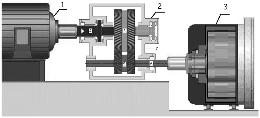
The invention discloses a high-inertia synchronous phase modifier device. According to the device, gear set equipment is connected with a synchronous phase modifier, a power output end is connected with energy storage flywheel equipment, and the inertia time constant of the whole phase modifier device can be increased; after the synchronous phase modifier is connected to a grid, when the frequency of the power grid rises, the rotating speeds of the rotor of the synchronous phase modifier and the energy storage flywheel equipment connected through the gear set equipment rise, the active power absorbed from the power grid is increased, and the rising of the frequency of the power grid is inhibited; when the power grid frequency is reduced, the rotating speeds of the rotor of the synchronous phase modifier and the energy storage flywheel equipment are reduced, the active power absorbed from the power grid is reduced or the active power is sent to the power grid, and the reduction of the power grid frequency is inhibited; the larger the inertia time constant of the whole phase modifier device is, the more stable the system frequency is. According to the device, the problem that the inertia time constant of the phase modifier is small can be solved, the mass of the flywheel can be reduced exponentially, the investment cost is reduced, and the engineering difficulty is reduced.

Description

technical field [0001] The present invention relates to the technical field of motors and electrical appliances, and more particularly, to a high-inertia synchronous camera condenser device. Background technique [0002] While the proportion of new energy has increased significantly, the trend of power electronics in the power system has become increasingly serious, and the voltage support, inertia support and frequency modulation capabilities of the power system have continued to weaken, seriously threatening the safe and stable operation of the power system. For this reason, GB 38755 "Guidelines for the Safety and Stability of Power Systems" released in 2019 requires that new energy stations should provide certain short-circuit capacity and inertia support to the system; Regulation resources such as power stations, pumped storage power stations, and energy storage power stations, and dynamic reactive power adjustment equipment such as condensers, static synchronous compens...

Claims


Application Information

Patent Timeline
IPC IPC(8): H02J3/40H02J3/30H02J3/24H02K7/116
CPCH02J3/40H02J3/30H02J3/241H02K7/116Y02E60/16
Inventor 李志强王东阳孙华东郭强李文锋
Owner CHINA ELECTRIC POWER RES INST
Learn More