A double-row cycle stamping die

A cycle stamping and mold technology, applied in the field of stamping molds, can solve the problems of reduced service life of equipment, unbalanced pressure, affecting the quality of workpieces, etc., and achieve the effects of improved efficiency, balanced mold arrangement, and reduced stamping force

Active Publication Date: 2022-05-10
SOHBI CRAFT CHANGSHU
View PDF7 Cites 0 Cited by
  • Summary
  • Abstract
  • Description
  • Claims
  • Application Information

AI Technical Summary

Problems solved by technology

The above patent documents provide a single row of multiple stamping dies, the upstream and downstream pressures will be unbalanced, which will reduce the service life of the equipment and affect the quality of the workpiece

Method used


Image

  • A double-row cycle stamping die
  • A double-row cycle stamping die
  • A double-row cycle stamping die

Examples


Embodiment Construction

[0045] The accompanying drawings are for illustrative purposes only, and should not be construed as limitations on this patent; in order to better illustrate this embodiment, certain components in the accompanying drawings will be omitted, enlarged or reduced, and do not represent the size of the actual product; for those skilled in the art It is understandable that some well-known structures and descriptions thereof may be omitted in the drawings. Exemplary examples will be described in detail here.

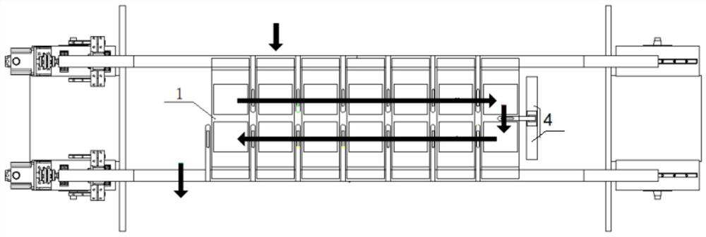
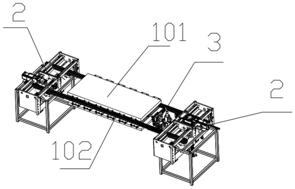
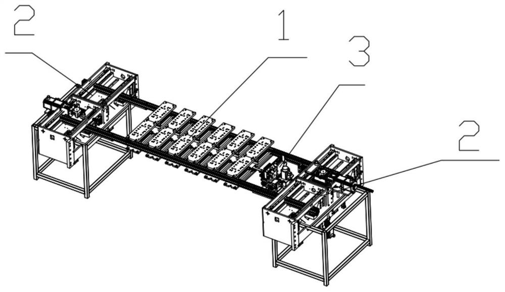
[0046] Such as Figure 1-3 and Figure 10 As shown, the present invention provides a double-row circulation stamping die, including a double-row circulation mold 1, a lateral transfer module 2 of the parts to be stamped outside the mold and a longitudinal transfer module 3 of the parts to be stamped inside the mold;

[0047] The double-row circulation mold includes a first group of circulation molds and a second group of circulation molds; the first group of circulation molds ...


PUM


Abstract

The present invention relates to the field of stamping molds, and provides a double-row circulation stamping mold, including a double-row circulation mold, a lateral transfer module for parts to be stamped outside the mold, and a vertical transfer module for stamping inside the mold; the double-row circulation mold includes the first A group of circulating molds and a second group of circulating molds; the first group of circulating molds includes n molds, which are respectively the first mold, the second mold, the third mold...the nth mold; the second group of circulating molds Including m molds, namely the n+1th mold, the n+2th mold, the n+3th mold...the n+mth mold, where m=n, the double-row molds are set on the same side for feeding and discharging The material, the mold layout is more balanced, which can reduce the stamping force and ensure the stamping balance, omitting the setting of the nitrogen resistance spring.

Description

technical field [0001] The invention belongs to the technical field of stamping dies, in particular to a double-row circulation stamping die. Background technique [0002] Single row of stamping dies, 1 set of equipment is equipped with n-channel molds (up to 8 channels), and the horizontal transfer module of the parts to be stamped outside the mold is used to realize the automatic production of products. The stamped parts to be processed generally enter from one end of the mold and exit from the other end . [0003] Compared with the previous project, the stamping force of the post-project will be smaller, and the mold of the post-project needs to add a resistance device to maintain the stamping balance. This will increase the stamping force of the mold and reduce the service life of the relative equipment. The transfer speed of the horizontal transfer module is fixed, and the speed can only be set according to the slowest working step. [0004] Patent document CN11146860...

Claims


Application Information

Patent Timeline
Patent Type & Authority Patents(China)
IPC IPC(8): B21D22/06B21D43/18
CPCB21D22/06B21D43/18
Inventor 张宁高健沈敏霞凌钰尹佳伟
Owner SOHBI CRAFT CHANGSHU
Why Eureka
Try Eureka