Intelligent adjusting system for axially aligning and positioning roller ring

An axial alignment and intelligent adjustment technology, which is applied in the parts of grinding machine tools, the control of workpiece feed motion, and machine tools designed for grinding workpiece rotating surfaces. Problems such as meeting the standards, not meeting the standards, etc.

Inactive Publication Date: 2021-11-30
重庆卓诚机械制造有限公司
View PDF1 Cites 0 Cited by
  • Summary
  • Abstract
  • Description
  • Claims
  • Application Information

AI Technical Summary

Problems solved by technology

[0004] The above scheme has the following disadvantages: hoisting the roller ring with a wire rope or a lifting chain, the lifting point is not easy to fix, and cannot meet the requirements of the heat treatment process for the workpiece to enter the furnace axially, so that the heat treatment furnace will not heat the workpiece uniformly, resulting in mechanical properties of the workpiece after heat treatment not to standard

Method used


Image

  • Intelligent adjusting system for axially aligning and positioning roller ring
  • Intelligent adjusting system for axially aligning and positioning roller ring
  • Intelligent adjusting system for axially aligning and positioning roller ring

Examples


Embodiment 1

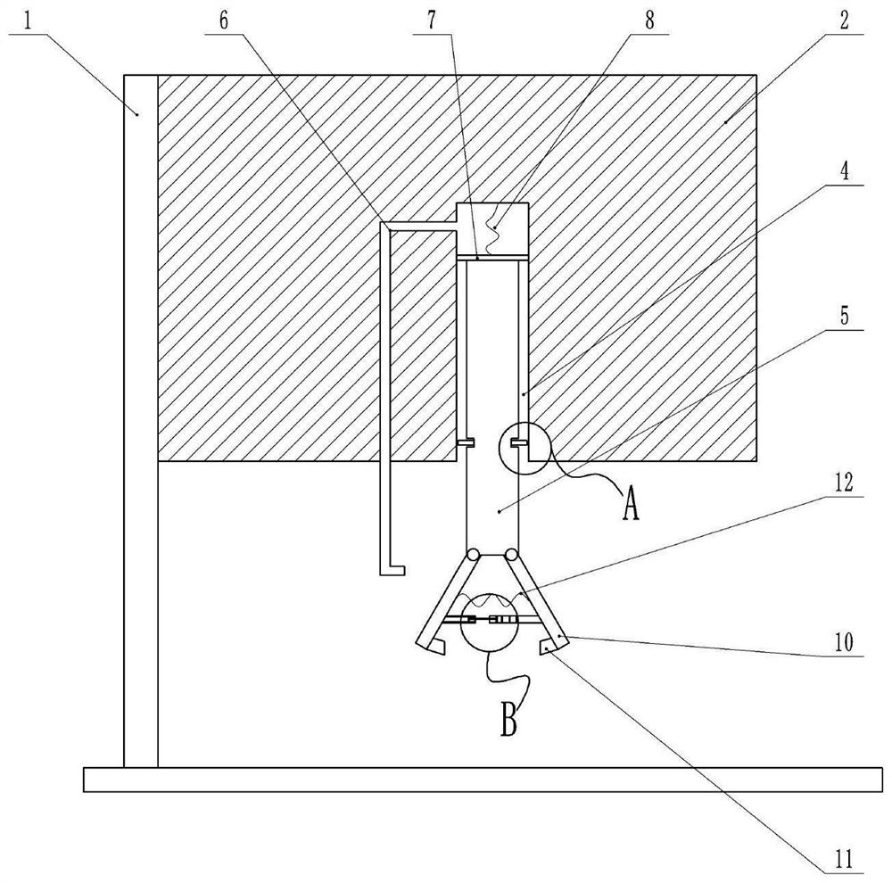
[0033] as attached figure 1 , attached figure 2 And attached image 3 Shown:

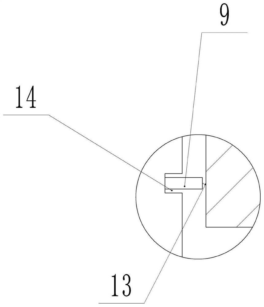
[0034] The frame 1 is provided with a clamp 2 for clamping the roll ring 22, and a suspension ring is provided directly above the clamp 2, which can lift the clamp 2 to ensure that the clamp 2 can be lifted or lowered by a machine or a lifting mechanism. The clamp 2 is provided with a cavity 4 and a connecting rod 5, and a groove 14 is provided on both sides of the connecting rod 5, and two spacer blocks 9 are arranged in the cavity 4, and the two spacer blocks 9 are connected with the cavity respectively. A third spring 13 is connected between the side walls of 4 , and the shape and position of the groove 14 and the limit block 9 are adapted to each other. The lower end of the connecting rod 5 is hinged with one end of the clip hook 10, one end of the two clip hooks 10 is hinged with the lower end of the connecting rod 5, and the other end can swing to adjust the closing angle of the two clip h...

Embodiment 2

[0044] as attached Figure 4 Shown:

[0045] The difference from Embodiment 1 is that this embodiment also discloses a process of grinding and spraying oil after the heat treatment of the roller ring 22. The barbs 11 are provided with rotating wheels 23 connected to each other. When the roller ring 22 is clamped, the runners 23 is in contact with the inner wall of the roller rim 22, the fixture 21 is provided with an oil injection pipe for spraying lubricating oil to the roller rim 22, the oil injection pipe is provided with a solenoid valve, and the fixture 21 is also provided with a grinding wheel for grinding the roller rim 22 21, the grinding wheel 21 is installed in rotation on the clamp 2, and the clamp 21 is provided with a driving mechanism 3 that drives the grinding wheel 21 to move up and down. The driving mechanism 3 can choose to drive the cylinder 15, etc., and the grinding wheel 21 is set correspondingly to the position of the clamp hook 10. To ensure that the g...


PUM


Abstract

The invention belongs to the technical field of roller rings, and particularly discloses an intelligent adjusting system for axially aligning and positioning a roller ring. The intelligent adjusting system further comprises a clamp; the clamp is arranged on a rack; the clamp is provided with two clamping hooks and a connecting rod, and one end of each clamping hook is hinged to the lower end of the connecting rod; and a cavity is formed in the clamp, grooves are formed in the two sides of the connecting rod, two limiting blocks are arranged in the cavity, third springs are connected between the limiting blocks and the side walls of the cavity, and the grooves are matched with the limiting blocks in shape and position. The roller ring is clamped by the clamping hooks, after the roller ring is clamped, the angle between the two clamping hooks is adjusted, when the connecting rod is pushed into the cavity, the connecting rod extrudes the limiting block and continues to move, when the groove moves to the position corresponding to the limiting block, the limiting block is not subjected to the extrusion force of the connecting rod any more, and the third spring rebounds, so that the limiting block is clamped into the groove, and then the connecting rod is limited. According to the scheme, axial deviation during roller ring machining can be reduced.

Description

technical field [0001] The invention relates to the technical field of roll rings, in particular to an intelligent adjustment system for axial alignment and positioning of roll rings. Background technique [0002] The roller ring is an important part of rolling ore in a mining pulverizer. It is a thick and short centrifugal casting workpiece. After it is cast, it needs to be heat treated to make its mechanical properties meet the requirements of use. [0003] The usual means of the traditional craft is to tie it up with a steel wire rope or a lifting chain for hoisting, and then send the roller ring axially into the heat treatment furnace, and the steel wire rope or lifting chain are heated together with the roller ring in the heat treatment furnace. The Chinese utility model patent with the application number CN201320432992.6 discloses a roller hoisting device, which includes a steel wire rope, a hanging beam, a lifting belt, a U-shaped lock, a fixed connecting rod and a su...

Claims


Application Information

Patent Timeline
Patent Type & Authority Applications(China)
IPC IPC(8): B24B5/36B24B55/00B24B49/00B24B41/06B24B41/02B24B49/16
Inventor 何棵
Owner 重庆卓诚机械制造有限公司
Why Eureka
Try Eureka