
Triage table monitoring system and non-contact physiological sign monitoring device

A monitoring system, non-contact technology, applied in diagnostic recording/measurement, diagnosis, pulse rate/heart rate measurement, etc., can solve the problems of long waiting time for patients, time-consuming, difficult operation of contact detection, etc., to improve the score The effect of diagnosis efficiency

Pending Publication Date: 2021-12-03
SHENZHEN MINDRAY BIO MEDICAL ELECTRONICS CO LTD
View PDF0 Cites 0 Cited by
  • Summary
  • Abstract
  • Description
  • Claims
  • Application Information

AI Technical Summary

Problems solved by technology

[0002] At present, during the triage at the triage station, preliminary examinations such as body temperature and heart rate must be carried out before the triage. For heart rate measurement, medical staff often need to obtain it through a stethoscope or press the pulse, which takes a lot of time
When there are many patients waiting for triage, it is often necessary to queue up or add multiple medical staff to form multiple triage positions for triage, which will either cause the patient to wait too long, or cause more medical staff to be deployed at the triage table personnel, resulting in a strain on medical resources
In particular, for some patients who are inconvenient to directly collect relevant signals through stethoscopes or electrodes or sensor connections, or for patients with emotional instability, there may be problems with the patient's lack of cooperation, and the contact detection operation is also relatively difficult

Method used


Image

  • Triage table monitoring system and non-contact physiological sign monitoring device
  • Triage table monitoring system and non-contact physiological sign monitoring device
  • Triage table monitoring system and non-contact physiological sign monitoring device

Examples


Embodiment Construction

[0021] The following will clearly and completely describe the technical solutions in the embodiments of the application with reference to the drawings in the embodiments of the application. Apparently, the described embodiments are only some, not all, embodiments of the application. Based on the embodiments in this application, all other embodiments obtained by persons of ordinary skill in the art without making creative efforts belong to the scope of protection of this application.

[0022] The terms "first", "second" and the like in the specification and claims of the present application and the above drawings are used to distinguish different objects, rather than to describe a specific order. Furthermore, the term "comprise", as well as any variations thereof, is intended to cover a non-exclusive inclusion. For example, a process, method, system, product or device comprising a series of steps or units is not limited to the listed steps or units, but optionally also includes...


PUM


Abstract

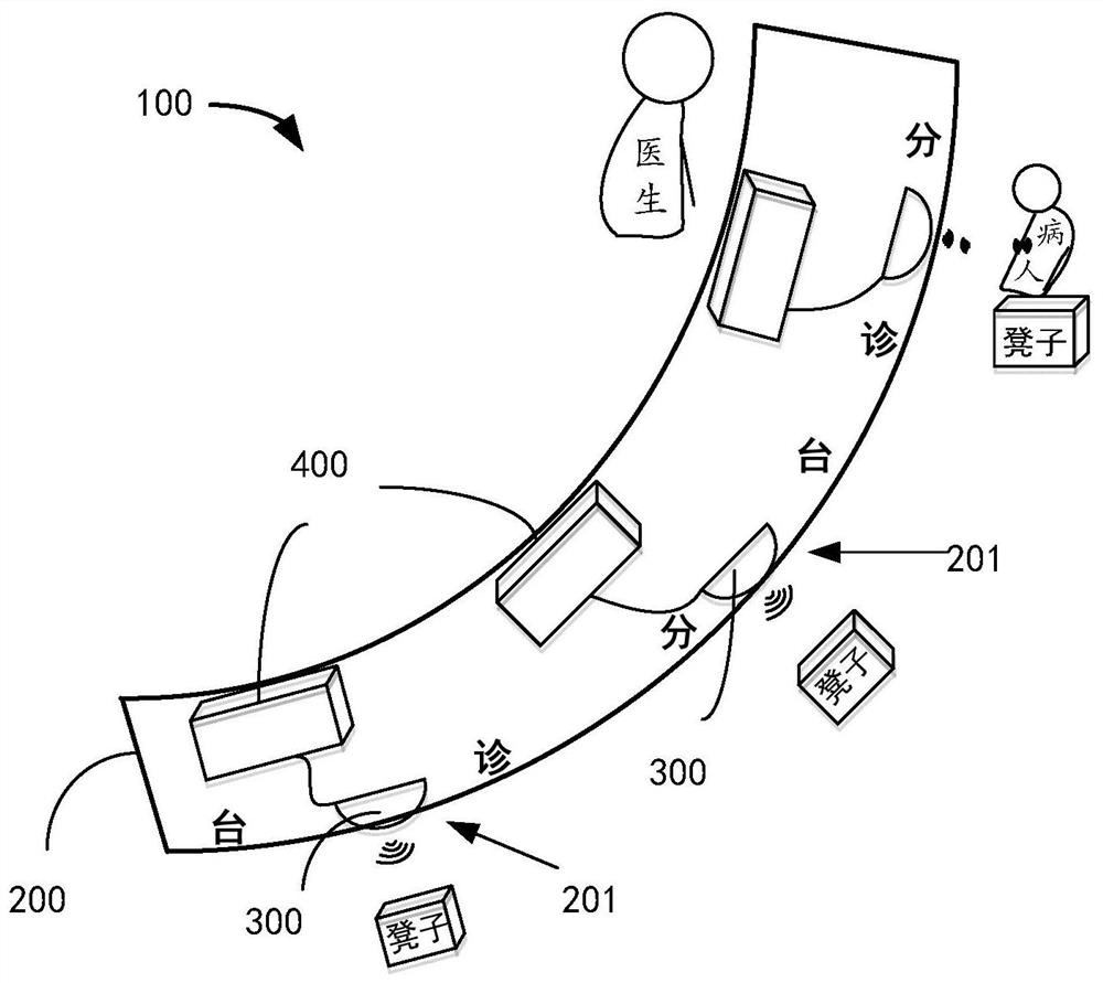
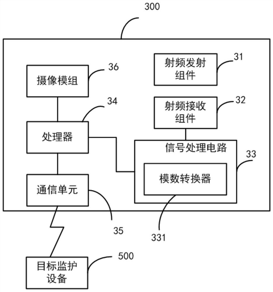
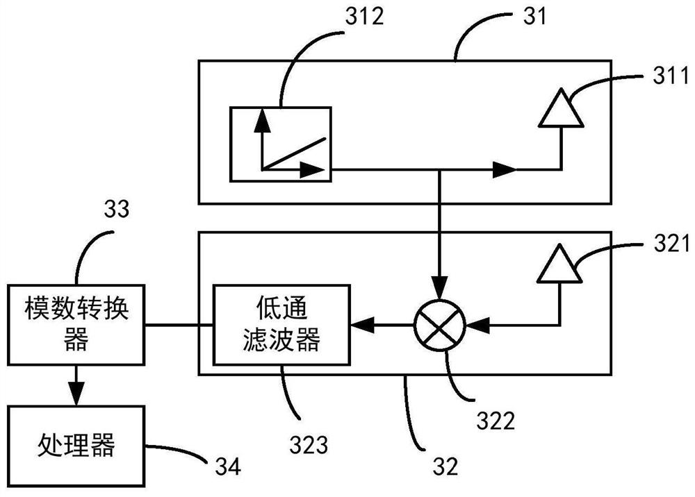
The invention provides a triage table monitoring system. The triage table monitoring system comprises a triage table with at least one triage position and at least one non-contact physiological sign monitoring device. The triage position is used for allowing a patient to be in place for preliminary examination before triage, the non-contact physiological sign monitoring device comprises a radio frequency transmitting assembly, a radio frequency receiving assembly, a signal processing circuit and a processor. The radio frequency transmitting assembly is used for generating electromagnetic waves with specific frequency and transmitting the electromagnetic waves towards the direction of the corresponding triage position. The radio frequency receiving assembly is used for receiving a reflection wave beam reflected by a specific body part of the patient at the triage position. The signal processing circuit is used for converting the reflected wave beam into a physiological parameter signal. The processor is used for analyzing the physiological parameter signals to obtain physiological parameter values and controlling and outputting the physiological parameter values. The invention further provides the non-contact physiological sign monitoring device. The triage efficiency can be effectively improved.

Description

technical field [0001] The present application relates to a monitoring device, in particular to a non-contact physiological characteristic monitoring device and a monitoring system for a triage table. Background technique [0002] At present, during the triage at the triage station, preliminary examinations such as body temperature and heart rate must be carried out before the triage. For heart rate measurement, medical staff often need to obtain it through a stethoscope or press the pulse, which is time-consuming. When there are many patients waiting for triage, it is often necessary to queue up or add multiple medical staff to form multiple triage positions for triage, which will either cause the patient to wait too long, or cause more medical staff to be deployed at the triage table personnel, resulting in a strain on medical resources. In particular, for some patients who are inconvenient to directly collect relevant signals through stethoscopes, electrodes or sensor co...

Claims


Application Information

Patent Timeline
IPC IPC(8): A61B5/0205A61B5/00A47B97/00A47B37/00
CPCA61B5/0205A61B5/6887A61B5/7445A61B5/7225A61B5/725A47B37/00A47B97/00A61B5/024A61B5/0816
Inventor 刘启翎谢军华岑建
Owner SHENZHEN MINDRAY BIO MEDICAL ELECTRONICS CO LTD
Learn More