Premixing burner for heat generator

A technology of pre-mixed combustion and heat generator, applied in the direction of burner, combustion chamber, combustion method, etc., can solve the problems of incomplete mixing, large gap, fluctuation, etc., and achieve the effect of improving the expansion angle

Inactive Publication Date: 2004-02-04
ALSTOM TECH LTD
View PDF0 Cites 0 Cited by
  • Summary
  • Abstract
  • Description
  • Claims
  • Application Information

AI Technical Summary

Problems solved by technology

[0005] c) Due to the above reasons, there is no overall thorough mixing from the start between the injection cone and the combustion air flow, which inevitably leads to nitrogen oxides (NO x ) increases in emissions;
[0006] d)

Method used


Image

  • Premixing burner for heat generator
  • Premixing burner for heat generator
  • Premixing burner for heat generator

Examples


Embodiment Construction

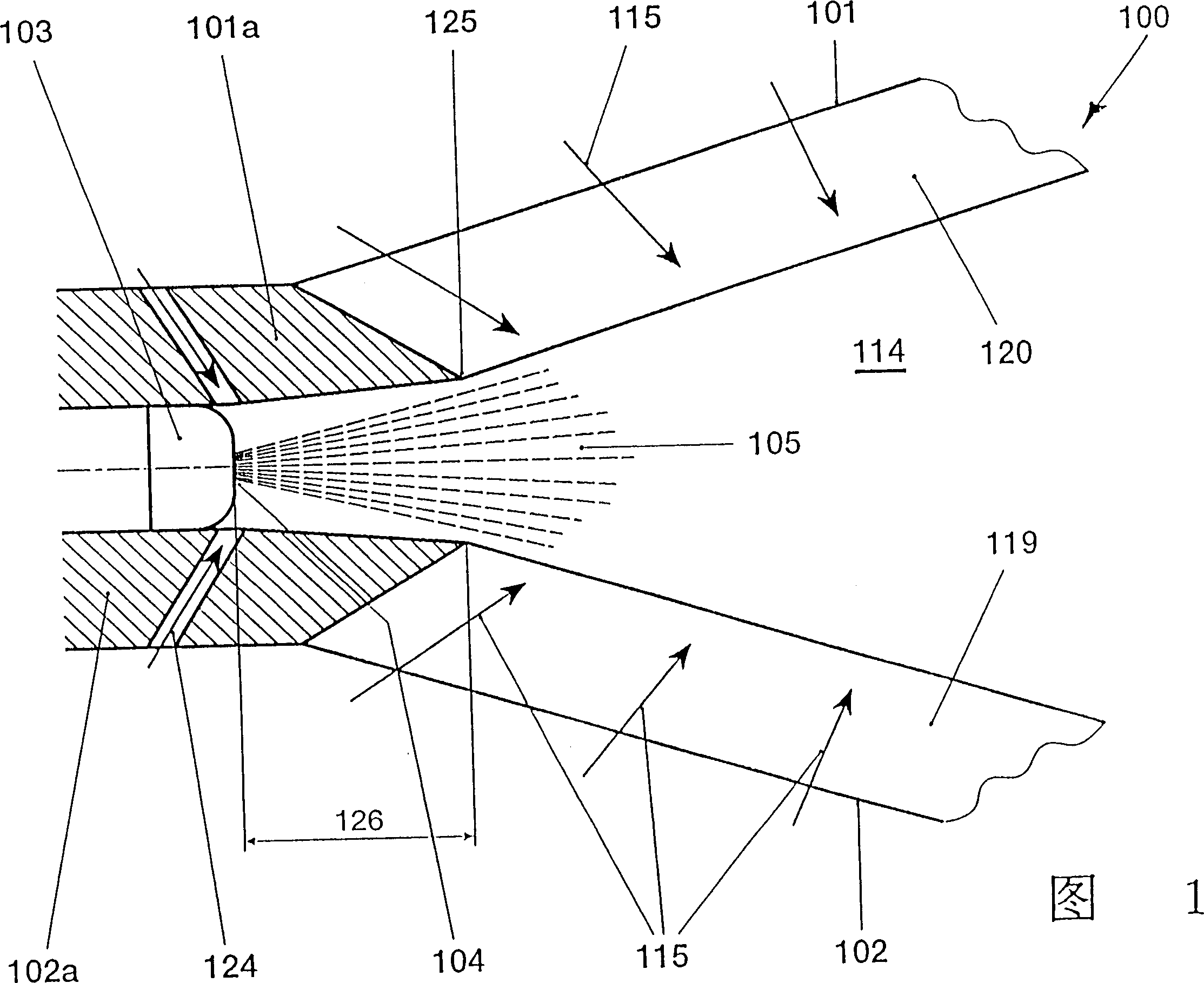
[0019] Figure 1 shows a schematic diagram of a premixing burner and is described in detail below with reference to Figures 2-5. 1 mainly shows a schematic diagram of a centrally positioned first fuel nozzle 103 that is offset upstream and rearwardly by a distance 126 with respect to the starting point 125 of the conical flow cross-section, which distance corresponds to the selected injection Angle 105 is about. As a result of this offset, the nozzle opening 104 of the first fuel nozzle 103 is located in the region of the head-fixed housings 101a, 102a. The fuel jet 105 generated by the backward displacement of the first fuel nozzle 103 enters the range covered by the main flow of combustion air in the burner inner chamber 114 with a larger conical radius, so the fuel jet 105 is no longer in this range as A dense solid, but breaks down into droplets, which easily pass through the combustion air stream. The flow of combustion air 115 into this fuel jet 105 is no longer hindere...


PUM


Abstract

In a premix burner (100) for a heat generator, which essentially comprises at least two hollow, conical sectional bodies (101, 102) nested one inside the other in the direction of flow, the longitudinal symmetry axes (101b, 102b) of the sectional bodies are offset from one another in such a way that the adjacent walls of these sectional bodies form air-inlet slots (119, 120), tangential in their longitudinal extent, for the throughflow of combustion air (115). On the head side, the premix burner (100) has a fuel nozzle (103) which is shifted upstream by a distance (126) relative to the cone start (125) induced by the sectional bodies. Thus the fuel injection is caught by the combustion air only when the fuel spray cone can be penetrated more effectively, which leads to better mixture formation.

Description

technical field [0001] The present invention relates to a premix burner. Background technique [0002] For swirl-stabilized burners such as those proposed in European patent EP-B1-0 321 809 as premixed burners, when a liquid fuel is sprayed onto the burner shaft, the liquid column formed by the fuel nozzle flows downstream It has a solid effect on the combustion air flow tangentially flowing into the interior of the premixing burner, especially in the initial section of the injection into the downstream. Combustion air inflow is blocked at the burner head, thereby intensifying the tangential component of the swirling flow to be formed, compared to an airflow without liquid fuel injection. This results in a change in the position of the flame which continues to move upstream. If a further fuel injection is carried out along the tangential air inlet slot, the operation of this fuel injection is extremely dangerous, since the flame front acting in this area inevitably leads t...

Claims


Application Information

Patent Timeline
IPC IPC(8): F23R3/20F23C7/00F23D11/24F23D11/40F23D17/00F23R3/28
CPCF23D11/402F23C7/002F23D17/002F23C2900/07002
Inventor H·P·克诺费尔T·卢克
Owner ALSTOM TECH LTD
Why Eureka
Try Eureka