
Wing structure and tilt rotorcraft

A wing and configuration technology, applied in rotorcraft, wing adjustment, motor vehicles, etc., can solve problems such as overload, reduce additional loads, avoid structural stiffness and stability problems, and improve efficiency.

Active Publication Date: 2021-12-03
NANJING UNIV OF AERONAUTICS & ASTRONAUTICS
View PDF6 Cites 2 Cited by
  • Summary
  • Abstract
  • Description
  • Claims
  • Application Information

AI Technical Summary

Problems solved by technology

Most of the existing tiltrotor wings remain fixed, so when the tiltrotor hovers and transitions, the wings are affected by the downwash of the rotor, which will cause serious overload

Method used


Image

  • Wing structure and tilt rotorcraft
  • Wing structure and tilt rotorcraft
  • Wing structure and tilt rotorcraft

Examples


Embodiment 1

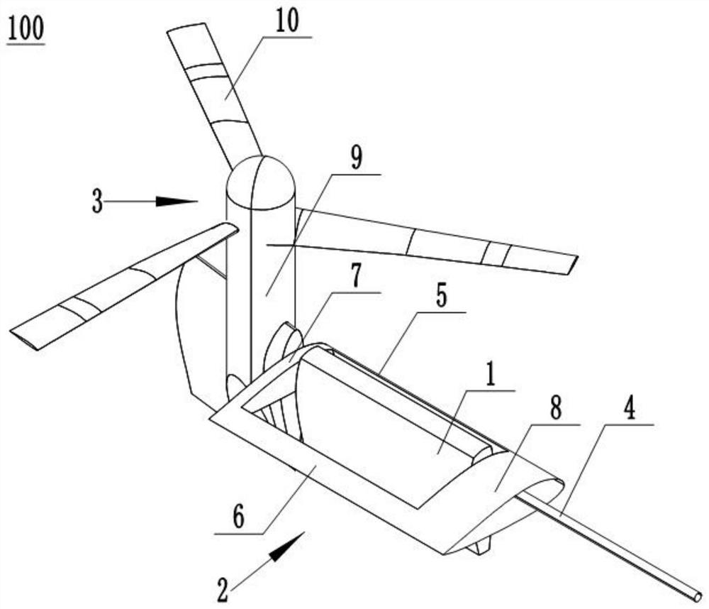
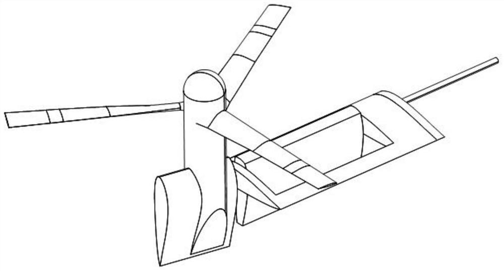
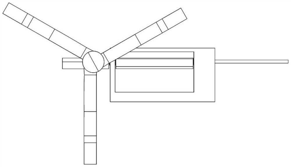
[0033] like Figure 1-Figure 4 As shown: this embodiment provides a wing configuration 100, including an outer wing 1, an outer wing frame 2, a rotor 3 and an intermediate beam 4, the outer wing 1 is arranged in the outer wing frame 2, and the rotor 3 is located at the outer end of the outer wing frame body 2, and the middle beam 4 passes through one end of the outer wing frame body 2, the outer wing 1, and the other end of the outer wing frame body 2, and then connects with the rotor 3, and the middle beam 4 Rotately connected with the outer wing frame body 2, the outer wing frame body 2 is used to connect with the wing body 12, the outer wing 1, the outer wing frame body 2 and the wing body 12 form a wing. The rotor 3 and the outer wing 1 rotate around the axis of the middle beam 4. The outer wing 1 of this embodiment tilts with the tilt of the rotor 3, which can effectively reduce the additional load on the wing caused by the downwash. It can also avoid potential safety ha...

Embodiment 2

[0043] like Figure 11-Figure 13 As shown: the present embodiment provides a tilt rotor aircraft 200, including a fuselage 11, a wing body 12, an empennage 13 and two wing configurations 100 in Embodiment 1, and the wing body 12 is arranged on the fuselage 11 The empennage 13 is arranged at the tail of the fuselage 11, and each wing configuration 100 is arranged at both ends of the wing body 12 respectively.

[0044] In this embodiment, the empennage 13 includes a vertical empennage 14 and a horizontal empennage 15 , the vertical empennage 14 is arranged vertically to the tail of the fuselage 11 , and the horizontal empennage 15 is arranged vertically to the vertical empennage 14 .


PUM


Abstract

The invention discloses a wing structure and a tilt rotorcraft and relates to the technical field of tilt rotorcrafts. The wing structure comprises an outer wing, an outer wing frame body, a rotor and a middle beam, wherein the outer wing is arranged in the outer wing frame body, the rotor is located at an outer end of the outer wing frame body, the middle beam sequentially penetrates through one end of the outer section wing frame body, the outer section wing and the other end of the outer section wing frame body and then is connected with the rotor wing, the middle beam is rotationally connected with the outer section wing frame body, and the outer section wing frame body is used for being connected with a wing body. According to the tilt rotorcraft, the additional load caused by underwash of the rotors to the wings can be effectively reduced, and efficiency of the tilt rotorcraft in the hovering and forward flying states is improved; and meanwhile, the outer section wing frame body can effectively avoid hidden dangers such as structural rigidity and stability problems caused by toppling of the outer section wing.

Description

technical field [0001] The invention relates to the technical field of tilt rotor aircraft, in particular to a wing configuration and the tilt rotor aircraft. Background technique [0002] The tilt rotor aircraft takes into account the advantages of both fixed-wing aircraft and conventional helicopters, and realizes the ability of vertical take-off and landing and high-speed cruising flight. It has broad application prospects in both military and civilian fields. Most of the existing tiltrotor wings are kept in a fixed state, so when the tiltrotor hovers and transitions to flight, the wings are affected by the downwash of the rotor, which will cause serious overload. Therefore, reducing the additional load of the rotor downwash on the wing is a key problem to be solved urgently in the development of the next generation of tilt rotor aircraft. Contents of the invention [0003] The purpose of the present invention is to provide a wing configuration and a tilt rotor aircra...

Claims


Application Information

Patent Timeline
Patent Type & Authority Applications(China)
IPC IPC(8): B64C3/36B64C3/40B64C27/26
CPCB64C3/36B64C3/40B64C27/26
Inventor 王博杨涛招启军林沐阳杜思亮陈希赵国庆张夏阳
Owner NANJING UNIV OF AERONAUTICS & ASTRONAUTICS
Learn More